Introduction
An extrude feature is based on a two-dimensional sketch. It linearly extrudes a sketch perpendicular to the sketching plane to create or remove material.
You can either select the sketch first or then start the Extrude tool, or you can start the Extrude tool and then select the sketch.
You can either select the sketch first or then start the Extrude tool, or you can start the Extrude tool and then select the sketch.
In this exercise we will try to learn about
- Solid Extrude
- Extrude cut/Add
- Extrude Thicken Cut/Add
- Tapper
Also we will use extrude types such as
- Blind
- Symmetric
- Through all
- Through until
- To selected
Let’s first discuss them and then we will do exercise.
Here is the dashboard option used in extrude tool. I label it to show you the function of the representative option.
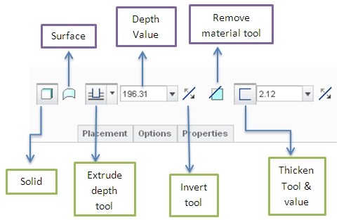
Solid: this option is selected by default to make solid extrude.
Surface: This can be used to extrude the sketch as surface.
Extrude depth tool: is used to control extrude by specifying some constraints.
Depth value: used to specify the dimension of depth. Some extrude types do not need this.
Invert tool: used to change the direction of extrude opposite to the reference direction.
Remove material: this tool is used to remove the material while extruding.
Thicken tool: is used to extrude as thick sheet. Thickness value can be adjust by entering the value in box (just right to the thicken tool). The invert tool next to the thicken tool is used to specify the direction of thickness by three ways.
- One side
- Both sides: thickness will be symmetric to the sketch boundary.
- Other side
When we click at the extrude depth tool a drop down menu will open in which you can see the following icons representing the specific conditions for extrude.one thing you should note that these option will be available when you will try to make extrude on existing surface or model.
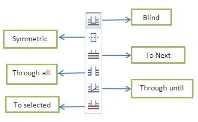
1) Blind: this is the default option. In simple words the depth is blind for program and we have to provide it.
2) Symmetric: This option provides you the equal extrude on the both side of sketching plane.
3) To next: using this option you can stop extrude to very next surface that extrude encountered. Depth dimension is not required for this option
4) Through All: This option will generate extrude that through to the whole model. Depth dimension is not required.
5) Through until: This option will cause extrude to stop at the specified/selected surface and section must pass through the selected surface.
6) To selected: it is just like the through until option except that section does not have to pass through the selected surface.
Now we have learnt the basics of extrude so it’s time to perform some exercise.
Solid Extrude
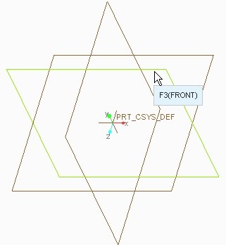
1) Select the front plane and click at extrude icon . It will get you into the sketching window.
2) Using a circle tool make a simple circle of your desired diameter (just for practicing) and click at ok button  .
.
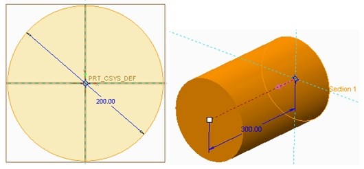
3) Now the creo parametric will show you the preview of your extrude. You can change the depth of extrude by moving the white square. To do this just click and hold at the white square and move your mouse to change the length.
Two types of extrude depth we can learn at this moment.
- Blind
- Symmetric
Blind option is shown in above figure and it is by default active. To use symmetric option click at “extrude depth tool menu” and select the symmetric option you will see that extrude become equally distributed with reference to sketching plane.
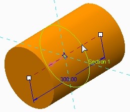
4) Now just click the ok button to complete a part of our exercise.
Extrude cut/Add
1) Now select the top surface of your previously extruded model and again click at extrude button.
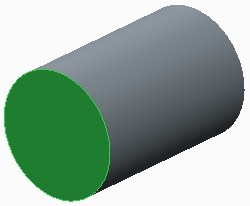
2) In sketching window again make a circle but this time its diameter should be less than the previous one. Click at ok button.
3) In extrude window if you want to add material than you can simply hit the ok button now.
4) If you want to remove the material than first you need to make sure that new extrude is going inside the model. You can do this by three ways. (1) By dragging the white square (2) by entering the negative length (3) by clicking at the invert button . Below in the figure you can see that I point out two arrows. These arrows can be used to change the extrude direction. Click on them and see what happen to extrude. For doing next exercise make it “solid extrude Add” (see the right pic in the following fig) then press ok .
.
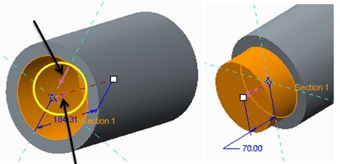
At this stage we will study two other types of extrude depth:
- Through all
- Through until
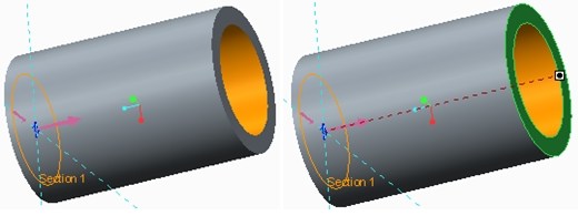
To use these options I suggest you to use extrude cut because of simplicity of our model. Click at through extrude icon and use extrude cut make the direction of extrude inside the model so we can observe the extrusion. As from definition of “through extrude” the cut will pass through the model making it a hollow cylinder.
To use “through until” and “to selected” just click on the respective extrude icon and specify the surface where you want to stop the extrusion. In this case I use extrude cut and select the select the cross-sectional surface opposite to the sketching surface. Both tools might work same in this case.
Left side figure shows “through all” and right side figure shows “through until”.
Thicken cut/Add
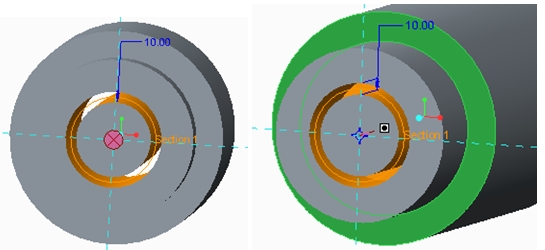
Now select the cross sectional surface of newly made extrude and click at extrude tool icon and in sketching window make another circle will smaller diameter then previous circle. After this press ok. In extrude window click at the “thicken tool icon”. Input some thickness value and click at invert tool next to the thicken tool again and again to observer the three states of thickness (that are mentioned earlier) shown in following figure. Note that section is highlighted with green color.

To use thicken cut option click at the “remove material” icon and place extrude into the model.
Now we will use extrude depth type “to next” and “through selected”. To use “to next” option while making thicken extrude cut, Just click at the “to next” extrude depth icon and you will observe that the cut move from front surface towards back surface. See the left side figure
To use through selected just click at its respective icon and select the front surface of our first solid extrude. The thicken cut will limit itself up to selected surface. See the right side figure.
Tapered
In tapered
- The sketch plane begins function as a pivot plane
- Positive and negative angles can be entered
- Positive direction of angle is determined by the sketch plane reference
To use tapered with other advance option of extrude, right click at extrude1 in model of creo parametric and click at “edit definition” option. This option will bring you in extrude window where you can modify it easily.
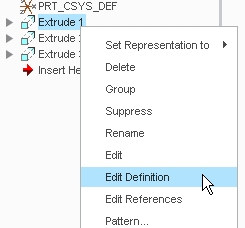
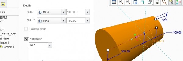
As this was the first extrude so keep it at default extrude depth i.e. “Blind” option. Now click at the option tab that you can see under the extrude dashboard.
In option tab you can specify the second side depth of extrude and to apply taper just check the taper check box and insert some value of angle and you will see the change in model accordingly.
No comments:
Post a Comment