Thursday 30 November 2017

HOW TO CONVERT ANY CAR INTO A HYBRID CAR AND INCREASE MILEAGE !!

Hybrid vehicles are popular all over the world but somehow have never managed to catch the fancy of buyer because of the higher costs. 

KPIT Cummins and Bharat Forge’s Joint Venture, Revolo, is in the final stages of developing hybrid kits which can exist alongside your conventional fuel systems and the increase the fuel efficiency by around 15-25%. A retrofit hybrid kit called Revolo which would have batteries as their heart would cost somewhere around Rs.70,000-Rs.1,50,000 depending upon  car  and the amount spent on the hybrid kits initially can be recovered by the consumers in a time frame of 2-3 years.

Cars with displacement capacities of 800 CC to 3,000 CC would get fitted with hybrid kits later in the day when the drafted policy gets a green signal from the concerned nodal authorities in the country.

The Hybrid cars get a start/stop system and the regenerative braking technique helps you save on your fuel bills as the efficiency of the car goes north. A car can be fitted with a hybrid kit within hours and in some cases the cars can even witness a faster pickup. The fuel prices are ever increasing and they are pretty much out of the control of a common man. But what can ease the pressure are the hybrid kits which will hit the cars soon and help you neutralize the effect of high fuel prices to a certain extent.

Wednesday 29 November 2017

NEW TECHNOLOGY: DYNAMIC DAMPING CONTROL EXPLAINED !!

Dynamic Damping Control (DDC) is a new technology that controls the working of suspension system of a vehicle electronically.  Normally the suspensions of a bike or a car works mechanically and they are not controlled by any other means. They work according to a predefined alignment once fixed. But in the Dynamic Damping Control (DDC) system, the valves inside the suspension are controlled electronically which enables to close and open itself according to different riding situations for providing better stability and comfortable ride.

The conventional system is a fixed one and it works the same for all real world situations like surface terrain, speed, turning, cornering, braking, accelerating etc. Let us see here in simple how an ordinary hydraulic damper works so it gives an idea to understand about the DDC technology.

The hydraulic damper- the one which is used as front fork suspension in motorcycles and also used in cars and trucks enclosed with springs called the Macpherson struts. These hydraulic dampers contains oil with two tubes sliding inside one another and it also has a piston inside.

Whenever a vehicle reaches a bumpy road or while cornering, the lower tube or mount takes the pressure and pushes it upward. During the upward movement, small valves in the piston opens due to higher pressure and transfers the oil to the upper side called as compression cycle. When the oil reaches the above position, a high pressure side is created on the upper tube or mount which forces the oil again to the lower side by using the valves in the piston called as extension cycle. The movements are equally balanced so it always regains its original position.

These dampers work depending only on the road conditions and they cannot adjust itself to different changing behaviours like sudden acceleration, braking, cornering etc. In order to resolve these factors the DDC technology is used.

DDC is the technology used by BMW. This technology can be otherwise called as adjustable damping since the dampers are adjusted electronically by a control unit similar to a working of fuel injection system.The DDC uses specially designed dampers which has electronically controlled valve system inside it. These valves are controlled by a DDC control unit. while braking, the DDC electronically activates the front damping valve proportionally to the deceleration, hence it provides optimal damping force and increases stability. 

As the bike leans during cornering, the suspension is gradually firmed up relative to the bike's lean angle making the cornering safe and stable. During low speeds the valves are actuated narrowly and it widens up as it reaches higher speeds.Thus the suspensions are activated depending on the different riding situations.

Within the shortest of times the system evaluates a huge amount of information and selects the high precision suspension configuration best suited to the situation. This provides a considerable boost to active riding safety, agility, operating comfort and riding fun. The suspension damping system DDC will be introduced to the first BMW Motorrad series motorcycles in the near future.

Monday 27 November 2017

TOP 5 BOOKS FOR CRACKING WRITTEN EXAMS AND INTERVIEWS IN MECHANICAL ENGINEERING !!

Being a competitive professional in one of the most dynamic fields in the world is not an easy task. That's why a mechanical engineer always needs to have reliable and up to date references on their desk. a good handbook on mechanical engineering design could be a real time saver.Here we are presenting Top 5 Mechanical Engineering handbook that will help in written examinations like GATE,PSUs etc. and also in interviews. 


1.)Mechanical Engineering (Conventional and Objective Type): Conventional and Objective Types by R.S. Khurmi 


A comprehensive text for undergraduate students of Mechanical Engineering and has successfully helped students to prepare for various competitive (such as GATE, UPSC and IES) as well as university examinations.


2.)A Handbook for Mechanical Engineering by Made Easy Editorial Board


The Handbook of Mechanical Engineering provides the crux of Mechanical Engineering in a concise form to the student to brush up the formulae and important concepts required for IES, GATE, PSUs and other competitive examinations. This handbook contains all the formulae and important theoretical aspects of Mechanical Engineering.


3.)Conventional & Objective Type Question & Answers On Mechanical Engineering for Competitions by  R.K. Jain


This book contains all questions that is required to crack interview and written examination.


4.)Objective Mechanical Engineering by P.K Mishra

Objective Mechanical Engineering is designed to be of help to the community of students pursuing mechanical engineering and aspiring to do so. The book starts with the basic concepts presented chapter-wise, followed by objective questions to test the reader's skills in engineering. Model test papers at the end help the students prepare for the exam thoroughly.


5.)Handbook of Mechanical Engineering by RPH Editorial Board

A concise book for candidates appearing for Mechanical Engineering Exams.


Most of these mechanical engineering books are well established and renowned handbooks in the field. There’s no doubt about their importance for the professionals. However, you might have even better books that you already use. It’s time to write in with what you have to say about the best mechanical engineer’s handbooks.

DIFFERENCE BETWEEN EVAPORATION AND VAPORIZATION EXPLAINED !!

Though the two processes, evaporation and vaporization, sound similar in meaning, there is some difference between vaporization and evaporation. When we closely look at those two processes at molecular level, we can realize that these two processes have distinct features and they are not identical. Both evaporation and vaporization take place in liquids by escaping molecules from the liquid phase to its gas phase, but in two different ways. Vaporization is a surface process whereas the evaporation is a bulk process. In this article, we will discuss the features in each process and compare them in order to find the differences between vaporization and evaporation in terms of how they occur and what are the special features in the process.

What is Vaporization?

Vaporization is a spontaneous process which occurs at the surface of a liquid. It is the conversion of a liquid to its vapor; it is the reverse of the process of condensation. The rate of vaporization increases as the temperature increases.Vaporization depends on the external factors such as wind speed, humidity, temperature and the surface area of the liquid. Vaporization takes place at a faster rate when the external pressure is low. When evaporation takes place, the external environment gets cool down, because heat is absorbed for this process to occur.
What is Evaporation?
Evaporation is a phase transition, where liquid phase changes to its gas phase at its boiling point. Evaporation is independent of the temperature, but it depends on the atmospheric pressure since the boiling point mainly depends on the atmospheric pressure. Different liquids have different boiling points and it depends on the strength of intermolecular forces. When the vapor pressure of a liquid equals to the external pressure upon the liquid, it starts to boil. This is called evaporation and it depends on the atmospheric pressure. 
Summary:
1.Vaporization is a transitional phase of an element or compound from a solid phase or liquid phase to a gas phase while evaporation is a type of vaporization wherein the transition from a liquid phase to a gas phase takes place below the boiling temperature at a given pressure, and it occurs on the surface.
2.Vaporization changes the phase or state of matter from a solid or liquid to a gas while evaporation changes the liquid state of matter into a gas.
3.Vaporization can occur with boiling, sublimation, or evaporation while evaporation can happen with the right amount of heat, humidity, and air movement.

Sunday 26 November 2017

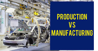
DIFFERENCE BETWEEN PRODUCTION AND MANUFACTURING EXPLAINED !!

Manufacturing and Production are often used as same terms but there is a big difference between them.We make no attempt to question why there are some manufacturing units while there are also production units. Why is it called milk production and manufacturing of automobile parts and why is it not milk manufacturing and production of automobile parts? Is there any difference between the two words or are the differences cosmetic and related with usage only? Let us take a closer look.

Manufacturing is the process of transforming raw materials into ready goods, with the help of machinery. On the other hand, production alludes to the processes or methods, that converts inputs like raw material or semi finished goods, to make finished product or services, which may or may not use machinery.

Manufacturing

Manufacturing is a process of using machines and manual labor to make goods that are sold to end consumers. Manufacturing is a generic word as it is used for very small scale companies making bakery goods though it is also used for a manufacturing unit making Boeing aircrafts. Paints are always manufactured and units making chemicals are also called manufacturing units.
Production
Making use of raw materials to transform it onto a finished product is termed as production. When something tangible is taken as raw material and transformed to turn it into a finished good, the process is termed as production.Steel is produced and not manufactured which is because of the fact that steel production involves making use of iron as a raw material and then transforming it into the finished good called steel.

Conclusion

Nowadays the creation of the product is very difficult. Input has to pass from many levels and hands to become the output. Moreover, the coordination of men, money, material and machine is also necessary. In manufacturing, the involvement of machines and raw material should be there. On the other hand, production is just a creation of utility, i.e. anything produced or transformed that adds utility to the consumer is known as production. In this way, it has no relation to raw material and machines.

Saturday 25 November 2017

STRESS STRAIN CURVE EXPLAINED !!

Stress strain curve is the plot of stress and strain of a material or metal on the graph. In this the stress is plotted on y axis and its corresponding strain on the x axis. After plotting the stress and its corresponding strain on the graph, we get a curve, and this curve is called stress strain curve or stress strain diagram.
The stress strain curve for different material is different. It may vary due to the temperature and loading condition of the material.
From the diagram one can see the different mark points on the curve. It is because, when a ductile material like mild steel is subjected to tensile test, then it passes various stages before fracture.

These stages are;
  1. Proportional Limit
  2. Elastic Limit
  3. Yield Point
  4. Ultimate Stress Point
  5. Breaking Point
PROPORTIONAL LIMIT
Proportional limit is point on the curve up to which the value of stress and strain remains proportional. From the diagram point is the called the proportional limit point or it can also be known as limit of proportionality. The stress up to this point can be also be known as proportional limit stress.
Hook’s law of proportionality from diagram can be defined between point OP. It is so, because OP is a straight line which shows that Hook’s law of stress strain is followed up to point P.
ELASTIC LIMIT
Elastic limit is the limiting value of stress up to which the material is perfectly elastic. From the curve, point E is the elastic limit point. Material will return back to its original position, If it is unloaded before the crossing of point E. This is so, because material is perfectly elastic up to point E.
Generally people confuse a lot between proportional and elastic limit.Up to proportional limit material returns to its original shape (so in graph it is linear )but in elastic limit up on removal of load material returns to its original shape witha little deformation (so in graph it is non linear).
YIELD STRESS POINT
Yield stress is defined as the stress after which material extension takes place more quickly with no or little increase in load. Point Y is the yield point on the graph and stress associated with this point is known as yield stress.
ULTIMATE STRESS POINT
Ultimate stress point is the maximum strength that material have to bear stress before breaking. It can also be defined as the ultimate stress corresponding to the peak point on the stress strain graph. On the graph point U is the ultimate stress point. After point U material have very minute or zero strength to face further stress.
BREAKING STRESS (POINT OF RUPTURE)
Breaking point or breaking stress is point where strength of material breaks. The stress associates with this point known as breaking strength or rupture strength. On the stress strain curve, point B is the breaking stress point.
How to Draw Stress Strain Curve or Diagram
  • A tensile test is done on the material for the drawing the stress strain curve. A specimen of specific dimension is taken generally a circular rod. A tensile test is than conducted on this rod by the use of tensile testing machine.
  • In this test, the specimen is fixed at one ends and tensile load is applied on the other end. The value of load and the extension in the rod is noted down. As we have noted down the load and extension, the stress and the corresponding strain can be easily calculated.
  • The formula that is used for the calculation of stress and strain are
  • σ ( stress ) =load/area of cross section
  1. strain=increase in length/original length
Where,
· σ = stress
· P = Load
· e = strain
· dL = extension produced in the rod
· L = original length
· A = cross section area
  • We plot a graph between the stress and strain and a curve is obtained. This curve so obtained is called the stress strain curve or stress strain diagram.
  • The stress strain curve for the same material is different for different temperature and loading condition of the material.
  • In the graph the slope represents the young's modulus of the material.

Friday 24 November 2017

ALL ABOUT MERCEDES BENZ : MULTIBEAM LED HEADLAMPS !!

The luxury car marquee Mercedes-Benz has always been a pioneer in the vehicle technology and their latest in headlight tech goes to show how dedicated the company is to improving and enhancing the safety of night time driving for not just the the person driving their cars but other road users as well. The new MULTIBEAM LED headlight technology  seen on the 2015 CLS-Class uses LEDs, on-board cameras, GPS, etc. to increase safety and provide better illumination. We explain how.

“This technology allows us to respond much faster to changes in our surroundings, and for example, to adapt the light to the new situation in the space of 10 milliseconds- something that was not possible before” says Mercedes-Benz development engineer Florian Herold. A total of four control units calculate the ideal light pattern 100 times a second. That is fast! Most normal road cars don’t even feature automatic headlamps which just goes to show how far ahead Mercedes has gotten in terms of technology. What this means is the on-board system is working constantly to enhance the driving experience and make night time driving safer in more ways than one.

Some key Features of MULTIBEAM LED headlight are :

Non-Dazzling High Beam:

One of the biggest features of the MULTIBEAM LED headlight tech is the non-dazzling high beam which ensures the driver of the on-coming vehicle is not blinded by the brightness of Mercedes’ headlamps.The new system however improves on this by forming a U-shape around the on-coming vehicle instead of blocking the beam to provide better illumination for the driver around the car without blinding the on-coming drivers.


Early Corner Recognition

The MULTIBEAM LED headlamp set-up comprises of another module for dipped beam consisting of four LED units. On-board cameras on the windscreen sense upcoming bends on the road before the steering wheel is turned. This information is relayed to the control module which calculates the angle of the bend and uses these LEDs to illuminate the corner by rotating them by up to 12 degrees. It also returns them to the straight ahead position once the bend has been negotiated. 


Roundabout Illumination Feature

The third highlight of the MULTIBEAM LEDs is the cornering light function with the roundabout feature. This feature works in tandem with the on-board navigation system and informs the control module of any upcoming roundabouts. Before entering the roundabout the left and right cornering lights are activated to provide wider illumination making it easier to spot on-coming cars, cyclists, pedestrians, etc.
The MULTIBEAM LED headlamp set-up currently only available on the 2015 CLS-Class but should slowly be rolled out in other models as well. Although, countries like the USA which have regulations requiring separate high beams and low beams will miss out in this feature.

Thursday 23 November 2017

DIFFERENCE BETWEEN TORQUE AND MOMENT EXPLAINED !!


The terms torque and moment originated with the study conducted by Archimedes on levers. Torque (most commonly used) or moment (used by engineers) is a concept of turning force. This turning force is applied when we push a door or try to open a nut using spanner. Both the door and the spanner turn about a point called the pivot or fulcrum. The force that is applied is at some distance from this fulcrum. The turning effect of the force applied depends upon this distance from the pivot or fulcrum.

Moment = Force* Perpendicular distance from the pivot
From this equation, it is clear that if we want to complete the task using less force, we have to increase the distance from the pivot.
In contrast, when a car driver turns a steering wheel, he exerts two equal and opposite forces on the steering. These forces form a couple and the turning effect of this couple is the sum of the moment of the two forces. The moment of a couple is called Torque.
Torque= Force*Perpendicular distance between the two perpendicular forces

In common parlance, Torque and moment are used interchangeably. Torque, or the moment of a force is its ability to rotate an object about an axis. While force is applied in torque as well, force is a push or a pull but in torque this force is in the form of a twist.
For the students of mechanical engineering, the two terms are different and not interchangeable. In general moment is the term used when referring to the ability of a force to turn an object about its axis. Torque is a special application of moment. When there are two equal and opposite forces, they form a couple, and the moment that results is called a torque. Here the applied force vectors are zero.
Summary:
1.“Moment” is a concept of engineering and physics that refers to the tendency of a force to move an object while torque is the tendency of a force to rotate an object in a pivot.
2.Moment is the perpendicular distance between the point of rotation and the force’s line of action while torque is a measure of the turning force of an object.
3.Torque is used to measure coupling while moment is not.
4.Both torque and moment have the Newton meter as the SI unit; torque is presented as Nm/revolution while moment is presented as Nm.
5.Moment is a static force while torque is a movement force.
6.Moment is used when there is no rotation while torque is used when there is rotation and a pivot.
7.Moment has the symbol “M” while torque has the Greek letter “tau” as its symbol.

Thursday 16 November 2017

WHAT DOES "LXI, VXI, ZXI" MEAN IN CARS? CHECK OUT THE ANSWER !!

Almost all car manufacturers have different variants available for the same car.
The car looks the same but will have different features inside and outside.
Maruthi uses L, V, Z alphabets. and their petrol and diesel variants are identified by XI and DI respectively.
Maruti: LXI, VXI, ZXI or LDI, VDI, ZDI
Honda: EMT, SMT, SVMT, VMT, VXMT, SAT, VAT, SCVT, VCVT etc


In honda, E, S, SV, V, VX are the variants and AT means automatic transmission and CVT means continuous variable transmission. so if a model says VCVT that means that the variant is and it has a CVT transmission in it.
In Honda cars petrol and diesel is identified by the separate markings iVTEC and iDTEC respectively

These are the different trim levels which is found in maruti suzuki vehicles.
Trim refers to the items that can be added to the interior and exterior of automobile to increase its appeal.
XI denotes petrol engine
LXI is for lower variant cars
VXI includes basic features like ac , power steering  etc
ZXI includes all the high end features  like ABS,Air bags,music player etc.

It is used for differentiating car models in maruti suzuki.
XI -  Petrol car
DI -  Diesel car
L -  Base model
V -  Full option model
Z -  Added features model

Now,
LXI is a base model Petrol car.
VXI is a full option Petrol car.
ZXI is a added features Petrol car

The same goes for LDI,  VDI,  ZDI. The only change is that it's a diesel car.

DIFFERENCE BETWEEN TWIST DRILL,STEPPED DRILL AND BURNISHING DRILL EXPLAINED !!

A Twist drill is a drill bit that has a Helical ( screw shaped ) flute cut into it for good swarf removal. It looks like a straight fluted drill bit has been twisted , hence the name.
A stepped drill is a special drill bit generally used to drill thin sections of a material. It is characterized by a series of increasing diameter cutting section which are stepped to specific diameters, allowing the user to drill to whatever diameter they need without having to drill a pilot hole and then change bits to work up to the required diameter of hole. It has a stepped conical profile.

A Burnishing drill generally has straight flutes and multiple stabilizing margin edges with a thinner pilot section at the tip that is followed by an extra set of burnishing margins . This allows very accurate sizing of the hole and the burnishing margins create a very fine finish on the inside of the hole. These drills are extremely precise when you need multiple holes that are very close in size to each other as they tend to be more rigid and do not deform under load like twist drills do.

DIFFERENCE BETWEEN STRESS AND PRESSURE EXPLAINED !!

Stress and pressure are the two important terms used frequently in the science and technology. Though they give same meaning, there are unique characteristics for each term. Pressure is defines as the amount of force applied per unit area.Stress is the amount of force per unit area experienced by a material.Although both have same units of newton/meter^2, they are different only in their context.


Major Differences are:

1. Pressure represents intensity of external forces acting at a point. but stress represent intensity of internal resisting forces develop at a point.


2. Pressure always acts normal to the surface. but but stress may also act either normal or parallel to the surface.


3. Magnitude of pressure at a point in all direction remain same. but magnitude of stress at a point in all the direction are unequal.


4. Pressure can be measured by using measuring device.like pressure gauge. but stress can't be measured directly by using any device.

Tuesday 14 November 2017

TECHNICAL TERMS OF 2-WHEELER EXPLAINED !!


1.)ANTI DIVE SYSTEM – A system installed with some brakes that uses front fork damping and the front brake assembly to prevent excessive fork compression and to improve handling when brakes are applied.

2.)AUTOMATIC TRANSMISSION – A transmission not using a manually operated clutch.

3.)AXLE – A shaft used to support a part or parts across the frame or forks. e.g., front and rear axles.

4.)BACK BONE FRAME – Frame which uses the engine as a structural member for load carrying.

5.)BEAD – The portion of the tyre which holds it onto the rim.

6.)BEZEL – Piece of metal surrounding head lights, gauges or similar components, sometimes used to hold the glass face of a gauge in the dashboard.

7.)BOOSTER PORT – In a two stroke engine, the port that allows an extra amount of air fuel mixture from the intake port into the combustion chamber.

8.)BRAKE FADE – Loss of braking power, usually caused by excessive heat after repeated brake applications.

9.)BRAKE LINE – Special hydraulic tubing made of steel, plastic or reinforced rubber. Hydraulic lines must be capable of withstanding extreme pressure without deforming.

10.)BRIDGED PORTS – A vertical port division in a two stroke cycle engine cylinder which allows use of a large port without the danger of ring or piston catching.

Thursday 9 November 2017

STRESS CONCENTRATIONS : CAUSE,EFFECT AND SOLUTION EXPLAINED !!

Stress concentration is the accumulation of stress in a body due to sudden change in its geometry. When there is a sudden change in the geometry of the body due to cracks sharp corners, holes and decrease in the cross section area, then there is an increase in the localised stress near these cracks, sharp corners, holes, and decreased cross section area. The body tends to fail from these places where the stress concentration is more. So to prevent a body from getting failed, the stress concentration should be avoided or reduced.It is also called as stress raisers or stress risers.

Cause:

The stress concentration in a body happens because of sudden change in the geometry of the body due to cracks, sharp corners, holes, decrease in the cross section area. Due to these irregularities, there is an increase in the intensity of stress in the body.

Effect

When a body has stress concentration in it, the chances of its failure increases. The body tends to fail from the place where it is has more concentration of stress. A body has less life that has more irregularities within it. In order to increase the life of the body, the intensity of stress should be reduced.

Stress concentration factor

The stress concentration factor is defined as the ratio of highest stress in the body to the reference stress. It is denoted by Kt.

Mathematically,
Where
σmax = Highest stress or maximum stress
σref = Reference stress
The value of stress concentration factor for
(i) A body free from irregularities is 1.
(ii) A body that has maximum irregularities or discontinuity is greater than 1.

Methods to Reduce Stress Concentration

1. There are no of ways to reduce stress concentration in a body and some of these are:
Avoiding sharp corners by providing a fillet radius at the sharp corners. By providing the fillet radius at sharp corners, the cross section area decreases gradually instead of suddenly. And this distributes the stress in the body more uniformly. This is shown in the figure given below.
2. By providing small holes near big hole. If we have an object, that has an internal hole within it. Then the intensity of stress near that hole is more. To avoid this, some smaller holes are created near that hole. This distributes the stress more uniformly than it was before. This is shown in the figure given below.
3. By decreasing the nominal diameter of a threaded object and make it equal to the core diameter. Suppose we have a threaded object. And the intensity of stress at threaded part is more. The chances of object may fail is more at the threaded part. This can be avoided by decreasing the nominal diameter of the shank and make it equal to the core diameter. This will distribute the stress more uniformly in the object with threads.
4. By providing notches or undercut at the sharp corners.

Monday 6 November 2017

CARBURETOR VS FUEL INJECTION SYSTEM EXPLAINED !!

Why do more and more motorcycles now a day have fuel-injection systems rather than carburetor?  

So here is our discussion Carburetor Vs Fuel Injection – Brief Discussion.
The carburetor is one of the most essential mechanical part on a motorcycle and many small engine machines. All engines require a proper mixture of air and fuel for combustion; this vital device known as the carburetor controls the ratio of the fuel/air mixture entering the engine.

The fuel injected system is controlled by a computerized fuel delivery system, while the ECU takes information from various sensors and determines how much fuel the engine receives based on this data. Other sensors deal with RPM, engine temperature, throttle position, and the crankshaft position.

Carburetor Vs Fuel Injection System :


  1. Fuel injector gives a slightly higher engine performance and slightly more efficiency when running at the best fuel-air ratio. Throttle response is also a bit better.
  2. Crucially, most carburetor problems can be fixed easily at the side of the road with an assortment of basic tools. An electronic fuel injection system, though, if it goes wrong, will usually require a new part – and that’s going to cost you. Repair is far more difficult. Today’s modern fuel injection systems require a computer to diagnose the problem.
Advantages of Carburetors:

* Easy to operate and cheap to replace.
* Quick servicing.
* On the go tuning and setting possible
* Can be opened up individually without disturbing the engine.

Disadvantages of Carburetors:

* Diaphragm inside is delicate and can tear which will end up to have it replaced.
* The tuning process needs a big screw driver and has to be done physically.
* There is a certain amount of lag in the process of fuel delivery.
Old technology.
* The air-fuel mixture ratio is not constant.

Advantages of Fuel Injection:

* Fuel delivery is optimum and fuel atomizing allows for complete combustion.
* Increase in fuel efficiency and power output.
* Acceleration sensitivity increases.
* The air fuel mixture can be changed on the go using different fuel maps pre-loaded on the ECU for variable power outputs.

Disadvantages of Fuel Injection:

* Servicing of the FI unit is cumbersome.
* If there is an ECU failure, the bike will seize to work.
* It costs a lot and the service and maintenance is costly as well.
* Producing new Fuel maps needs loads of expertise.
* Procuring new fuel maps is a costly affair.

It is fairly obvious that most automobiles will be changing to fuel injection systems due to the lower emissions. However, unless the cost of these systems decreases significantly then there will still be a massive following that will stick to carburetors. When looking at pure horsepower, the fuel injection system only delivers about 10 extra horsepower at peak.