Tuesday, 19 July 2016

ROTARY ENGINE (WANKEL ENGINE)

Introduction:-
The rotary engine is alternative of the reciprocating engine. It is developed by Wankel in the year 1957. In rotary type of engine the pressure
force generated by the combustion of fuel is exerted on a rotor. So the rotor revolves and converts the chemical energy of fuel into mechanical energy. This engine is compact and it has high power weight ratio, so this is widely used in submarines and helicopters. 


Main parts of Wankel rotary engine:

In Wankel rotary engine, some parts work together and achieve the goal of convert the energy. These parts are

Rotor:
In a rotary engine a triangular shaped rotor is used. It has three convex faces. Each faces act like a piston. The rotor works as the prime mover in the rotary engine. The force generated by the combustion of fuel is directly exerted on the rotor, so it rotates eccentrically. The rotor has an internal timing gear on one side, which mash with the fix timing gear, situated on the side housing to maintain correct relationship between rotor and eccentric shaft.
Housing:
The rotor spin in the oval shaped chamber known as housing. The function of housing is same as the function of cylinder in the reciprocating engine. Housing contains inlet and outlet port, spark plug, water jacket etc. The main housing is closed by use of side housing. Side housing contain a fix timing gear which mashes with the internal timing gear and maintain correct relationship between rotor and eccentric shaft. It is usually made by aluminum silicon alloy.

Eccentric shaft:
Eccentric shaft, which is also known as the output shaft is used to convert the eccentric motion of rotor into concentric motion and carry it out from engine.
Apex seal
All sides of triangular rotor works as the piston. So it is necessary to seal this entire chamber with one another. To fulfill this function, apex seal is used to each corner of rotor. It is gas tight sealing between rotor and housing. It is usually made by cast iron and sometime by high carbon steel.


Working of Wankel rotary engine:

The energy converting process in a Wankel rotary engine is divided into four processes. These are intake, compression, power and exhaust. All processes are going on at the same time around each rotor while the engine is running. The engine has three lobed. The rotor driven eccentrically in the casing in such a way that there are three separate volumes trapped between the rotor and the casing. These three volumes perform induction, compassion, combustion and exhaust processes in sequences.


Intake process:
Intake is mean to intake of air fuel mixture into the engine. When the lobe A moves, the space between lobe A and C expands. This cause air fuel mixture enters into engine through inlet port to fill the space. When the lobe C passes the intake port, the space between A and C sealed off.
Working of rotary engine
Compression process:
When the rotor revolves, the space between lobe A and B greatly reduced. So the mixture between lobe A and B compress.

Combustion process:
When the mixture between A and B compressed completely, a spark generate at the spark plug which ignites the mixture. It burn and force the rotor to turn. It is also known as power generating process.

Exhaust process:
When the lobe B passes the exhaust port the burn mixture exhausts.
These strokes of intake, compression, combustion and exhaust follow continuously in each 

Friday, 15 July 2016

BASICS OF AUTOMOBILE ENGINEERING

Automobile Engineering
Automobile engineering is an applied science that includes elements of Mechanical engineering, Electrical engineering, Electronic
Engineering, Software Engineering and Safety engineering as applied to the design, manufacture and operation of automobiles, buses and trucks and their respective engineering subsystems.
The word automobile comes, via the French automobile, from the Ancient Greek word (autos, "self") and the Latin mobiles ("movable"); meaning a vehicle that moves itself, rather than being pulled or pushed by a separate animal or another vehicle. The alternative name car is believed to originate from the Latin word carrus or carrum("wheeled vehicle)
What is an Automobile?
The automobile is a self propelled vehicle that travels on land. It usually has four wheels. An engine provides the power to move the vehicle. As the name implies, it is a mobile or moving power unit on road. Self- propelled means unit which contains its own power source, necessary for moving, within itself .As a vehicle ,it is used for transportation of passenger and goods.

HISTORY OF AUTOMOBILE DEVELOPMENT
The history of automobile development an growth is very fascinating. It runs together with the history of development of engines. This can studied as under.
European Development
 The awn of automobile history dates back to 1770 when a Frenchman, Nicholas Carnot, built the first road vehicle propelled by its own power. The French artillery officer built a three-wheeler steam tractor for handling a canon. It could work for 15 minutes only and attained a sped of about 2.5 mph.
The automobile or the car as we now today evolved from the horse-drawn carriage, and perhaps the 19th century tricycle; but as the years went by it gradually lost its likeness to any of its progenitors. The saga of the car really began as recently as 1860, when Jean Etienne Lenoir, a Belgian  inventor, built the first practicable gas engine. Etienne’s engine was fed on a mixture of coal gas and air and no compression meant that it was not efficient.
The next significant development came in 1876 when Count Nikolous Otto, a German engineer, successfully applied the four- stroke principle which enabled the charge to be compressed with significantly better performance. At about the same time petrol came to substitute the coal gas. During the 1880’s Germany was the hub of automobile development with Gottlieb Daimler and Carl Benz at the helms of affairs. They were building their cars for sale in 1886. The engine was placed in the front of the chassis, hooked up to a sliding gear transmission, brake pedal, clutch and acceleration were incorporated.
By the turn of the century, designers began increasing the number of the cylinder and a prototype in-line 6-cylinder engine appeared in 1902. The design improvement awakened the public to the next six years, production and sale of these vehicles became a business.
The early 1920’s saw the beginning of a  period of gradual change and refinement in automobile design. The spark ignition engine was the power plant of motor vehicle and kicked out steam and electrical rivals. Water-cooled engine were almost certain. The engine were located in the front of the chassis. The poppet valve was used in every engine design. Major improvements have been made in every car feature. The main design requirements emphasized on production of reliable vehicles to function at all times under all condition which would be increasingly comfortable to ride in and easy to operate.
 American Development
When Europe was struggling to make his vehicle run, came the period, in which the development of mass-production methods permitting lower prices played a dominant role in America. In 1908 Ford started off his Model T with an initial run of 2,000 vehicles, an output unheard of at that time. Ever since, the correlation of design and production efficiency has influenced the trend of modern vehicle construction and popularized the use of automobiles. The life of tyres has been increased, independent front-wheel suspension has been introduced; four-wheel hydraulic brakes have been incorporated, the higher compression ralios and availability of new materials have helped to enhance power-weight ratio.
Substantial progress has been made after the second world war in every car feature such as reliability and safety, ease and comfort, economy of operation, pleasing appearance. Safety and exhaust emission were the additional features. Research and development continue to produce computer controlled vehicles powered with nuclear engines and fuel cells.
Indian Development
At the end of 1900, the cars arrived in India and were used by Britishers and Kings of states. In pre-Independent India, cars were imported and it was only in 1946, Hindustan Motors was set up in Calcutta. It was followed by Premier Automobiles in 1947 to produce cars and Mahindra and Mahindra in 1949 to produce jeeps in Bombay. Standard Motors was established in Madras in 1950. The industrial giant, Tata introduced a plant for the manufacture was started in India with foreign collaborations and as such could not contribute much to improve the design and manufacture of new cars.
The production of all the cars was far below the nation’s demand. Maruti Udyog Limited was emphasized in 1982 in collaboration with Suzuki of Japan to manufacture small cars. It has helped to automobiles the country. New models have been introduced by various companies in recent years which have the latest features and machines available for all income group of the country’s population. The details of Indian automobile manufactures and specifications of their motor vehicles are listed in Appendix I.
VEHICLE OPERATION
There is a wide variety of motor vehicles but most of them perform their function in almost identical manner.
1. Rolling of Crankshaft
The driver turns on an ignition and starter switch. The battery starts supplying electrical current to a starting motor. The motor turns a flywheel and the crank shaft which are interconnected.
2. Running of Engine
The driver pushes the accelerator pedal to control the ate of flow of petrol into a carburettor. The carburettor helps to mix the petrol and air and prepares combustible mixture. This mixture is sucked into the engine cylinder and is compressed by the piston. An electric spark sets fire to the mixture and an explosion takes place. The high pressure of explosion pushes the piston out and the crankshaft and the engine start running. As the explosion process is repeated again and again, the crankshaft is disconnected from the starting motor and is turned continuously by the piston and connecting rod.
3. Transmission of Engine Power to Rear Wheels
Through a clutch, the driver connects the crankshaft to a set of gears (transmission). The power is thus transmitted from the engine to the rear wheels. By means of a gearshift lever, the driver shifts the gears of the transmission to suit driving conditions.
In case of vehicles equipped with automatic transmission, the driver selects the drive range for operation. The clutch and the selection of transmission gears are operated automatically.
4. Turning a Corner
The gear box is connected to a propeller shaft through a universal joint. As the transmission gears change, the propeller shaft is set into motion. The other end of propeller shaft is connected to the rear axle through a set in to motion. The other end of propeller shaft is connected to the rear axle through a set of bevel gears. The motion is turned at rightangles and thence to the rear wheels which are directly mounted on the rear axle.
The differential which is a set of gears is arranged in the rear axle and permits one rear wheel to turn faster than the other. This is necessary as and when turning a corner.
5. Control of Vehicle Motion
The motor vehicle is in motion and rolls along the road. The driver controls the direction of the vehicle by turning the front wheels with the help of a steering gear.
The driver is ready to slow down the vehicle or stop it with the help of a braking system.
6. Distribution of Vehicle weight
The order of the vehicle can experience the jolts by its forward movement and jerks due to unevenness of the road surface. These jolts and jerks are partially controlled by the spring mountings of front and rear axles, shock absorbers which dampen out sudden recoils in the springs, the padding and springs in the vehicle seats. The side swings are decreased by the chassis cross members and proper distribution of the weight of the chassis and the body between the front and the rear wheels.
SYSTEMS OF A VEHICLE
A motor vehicle has to perform meeting complex requirements. The main requirements expected from a modern automobile can be enumerated as follows:
1. Reliability and Safety
The vehicle should give long and trouble-free running with maximum safety features,
2. Ease and comfort
It should be easy to operate and park and running should be comfortable, without noise, vibration, pollution, heat and humidity.
3. Economic of operation
It should be cheap, fuel-efficient, maintenance free. Fuel, consumables, spare parts, labour should be easily available at low cost.
4. Maneaurability
It should be easy to drive the vehicle inside a city, on the highways and hills.
5. Appearance
The shape, size and colour should be pleasing. It should need minimum space for parking.
There are a large number of systems and parts used in a modern automobile to meet the above complex requirements.
Motor vehicles, both passenger and truck, are generally made up of two major assemblies, i.e., a chassis and a body.
(a) Chassis: It contains all the major units necessary to propel the vehicle, direct its motion, stop it and allow it to run over uneven surfaces;
A vehicle arrangement without body is called chassis (Chassis =Automobile-Body)
(i) The frame
(ii) The engine
(iii) The transmission system
(iv) The wheels and tyre assembly

AIR BRAKES

Introduction:-
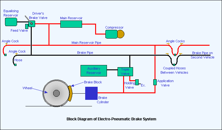
The operation of air brakes is similar to the hydraulic brakes except that in their case compressed air is used to apply brakes instead of
hydraulic pressure. Air brakes are commonly used on heavy vehicles, like trucks, buses etc.
Use of air brake in trains

The complete layout circuit is shown in figure. The compressor takes air from the atmosphere through the filter and the compressed air is sent to the reservoir through the unloaded valve. The valve gets lifted at a predetermined reservoir pressure (about 900 kPa) and relieves the compressor of load. From the reservoir the air goes to various accessories and to the brake chambers located at each wheel. the control of brake valve is with the driver who can control the intensity of braking according to the requirements. When the brakes are applied, the air pressure in the reservoir decreases. When the pressure drops to 700kPa, the governor again cuts in the compressor to raise system pressure. When air system pressure falls to about 400kPa, a warning in the form of a buzzer, is sounded.

The main components of air brake system are :
1. Air compressor with air filter to compress atmosphere air.
2. Unloader valve to maintain a set pressure.
3. Air reservoir to store compressed air at specified pressure.
4. Brake valve to control the intensity of braking.
5. Brake chambers are installed at each wheel to convert air pressure into useful mechanical energy.

Advantages of air brakes
1. Air brakes are more powerful than mechanical or hydraulic brakes, are exclusively used in heavy vehicles.
2. The air brake simplifies the chassis design. The components of the system can be located on the chassis any where and are interconnected by a pipe line.
3. Apart from braking, the compressed air from the reservoir can be used for tyre inflation, windscreen wipers, horns and many other accessories.

Disadvantages of air brakes
1. Air brakes involve more parts.
2. Air compressor uses engine power.

Thursday, 14 July 2016

RAMJET ENGINE

Introduction :-
The ramjet engine is an air breathing engine which operates on the same principle as the turbojet engine. Its basic operating cycle is
similar to that of the turbojet. It compresses the incoming air by ram pressure, adds the heat energy to velocity and produces thrust. By converting kinetic energy of the incoming air into pressure, the ramjet is able to operate without a mechanical compressor. Therefore the engine requires no moving parts and is mechanically the simplest type of jet engine which has been devised. Since it depends on the velocity of the incoming air for the needed compression, the ramjet will not operate statistically. For this reason it requires a turbojet or rocket assist to accelerate it to operating speed.


Ramjet Engine

At supersonic speeds the ramjet engine is capable of producing very high thrust with high efficiency. This characteristic makes it quite useful on high speed aircraft and missiles, where its great power and low weight make flight possible in regions where it would be impossible with any other power plant except the rocket. Ramjets have also been used at subsonic speeds where their low cost and light weight could be used to advantage.


Principle of Operation: 
The ramjet consists of a diffuser, fuel injector, flame holder, combustion chamber and exit nozzle . The air taken in by the diffuser is compressed in two stages.The external compression takes place takes place because the bulk of the approaching engine forces the air to change its course. Further compression is accomplished in the diverging section of the ramjet diffuser. Fuel is injected into and mixed with air in the diffuser. The flame holder provides a low velocity region favourable to flame propagation, and the fuel-air mixture recirculates within this sheltered area and ignites the fresh charge as it passes the edge of the flame holder. The burning gases then pass through the combustion chamber, increasing  in temperature and therefore in volume. Because the volume of air increases, it must speed up to get out of the way off the fresh charge following behind it, and a further increase in velocity occurs as the air is squeezed out through the exit nozzle. The thrust produced by the engine is proportional to this increase in velocity.

Working Principle of ramjet engine
Advantages
1. Ramjet is very simple and does not have any moving part. It is very cheap and requires almost no maintenance.
2. Since turbine is not used the maximum temperature which can be allowed in ramjet is very high, about 20000 C as compared to about 10000 C in turbojets. This allows a greater thrust to be obtained by burning fuel at A/F ratio of about 15.1 which gives higher temperatures.
3. The SFC is better than turbojet engines at high speed and high altitudes.
4. There seems to be no upper limit to the flight speed of the ramjet.
Disadvantages
1. Since the compression of air is obtained by virtue of its speed relative to the engine, the take-off thrust is zero and it is not possible to start a ramjet without an external launching device.
2. The engine heavily relies on the diffuser and it is very difficult to design a diffuser which will give good pressure recovery over a wide range of speeds.
3. Due to high air speed, the combustion chamber requires flame holder to stabilise the combustion.
4. At very high temperature of about 20000 C dissociation of products of combustion occurs which will reduce  the efficiency of the plant if not recovered in nozzle during expansion.
Application: 
Due to its high thrust at high operational speed, it is widely used in high speed aircrafts and missiles. Subsonic ramjets are used in target weapons, in conjunction with turbojets or rockets for getting the starting torque. 


CENTRIFUGAL PUMP

Introduction:-

Centrifugal pumps are the most preferred hydraulic pumps used in domestic and industrial world.Centrifugal pumps are used to transport fluids
by the conversion of rotational kinetic energy to the hydrodynamic energy of the fluid flow. The rotational energy typically comes from an engine or electric motor. The fluid enters the pump impeller along or near to the rotating axis and is accelerated by the impeller, flowing radially outward into a diffuser or volute chamber (casing), from where it exits
Centrifugal Pump
Working Principle :-

Centrifugal pumps rely on centrifugal force as the fundamental principle by which they operate. Centrifugal force affects an object or material moving in a circular pattern by causing it to pull away from the central axis or center point of the path along which it travels. This force can be used to regulate the pressure and motion within a pumping unit, and when applied in combination with a number of other centrifugal pumping principles, forms an integral part of hydraulic mechanisms.

In centrifugal pump there is an impeller. It has a series of curved vanes fitted inside the shroud plates. The impeller is always immersed in the water. When the impeller is made to rotate, it makes the fluid surrounding it also rotate. This imparts centrifugal force to the water particles, and water moves radially out.


Impeller

Since the rotational mechanical energy is transferred to the fluid, at the discharge side of the impeller, both the pressure and kinetic energy of the water will rise. At the suction side, water is getting displaced, so a negative pressure will be induced at the eye. Such a low pressure helps to suck fresh water stream into the system again, and this process continues.


Working of centrifugal pump


Wednesday, 13 July 2016

CLUTCH AND ITS TYPE

Introduction:-
Clutch is a mechanical device which is used to transmit power from driving shaft to the driven shaft or we can say that clutch is defined
as the device which is used in automobiles to transmit power from one rotating shaft to another shaft. In cars it transmits power from the flywheel connected to the engine shaft to the clutch shaft, and from clutch shaft it is transmitted to the rear wheels through gear shaft, propeller shaft and differential.


Mainly clutches are divided into 2 parts:

  1. Friction clutches and
  2. Fluid flywheel

Friction clutches:

These clutches works on the principle of friction exist in between two rotating shaft when they come in contact with each other.

Fluid flywheel:

Fluid flywheel clutches works on transfer of energy from one rotor to the other by means of some fluid.

Types of friction clutches:

  1. Cone clutch
  2. Single plate clutch
  3. Multi-plate cutch
  4. Semi-centrifugal clutch
  5. Centrifugal clutch

1.) Cone clutch:

It is a friction type of clutch. As the name, this type of clutch consist a cone mounted on the driven member and the shape of the sides of the flywheel is also shaped as the conical. The surfaces of contact are lined with the friction lining. The cone can be engage and disengage form flywheel by the clutch pedal.
Cone Clutch

2.) Single plate clutch:

In the single plate clutch a flywheel is fixed to the engine shaft and a pressure plate is attached to the gear box shaft. This pressure plate is free to move on the spindle of the shaft. A friction plate is situated between the flywheel and pressure plate. Some springs are inserted into compressed position between these plates. When the clutch pedal releases then the pressure plate exerts a force on the friction plate due to spring action. So clutch is in engage position. When the driver pushes the clutch pedal it due to mechanism it serves as the disengagement of clutch.

Single plate clutch

3.) Multi-plate clutch:

Multi-plate clutch is same as the single plate clutch but there is two or more clutch plates are inserted between the flywheel and pressure plate. This clutch is compact then single plate clutch for same transmission of torque.

Mutliplate Clutch

4.) Centrifugal clutch:

As the name in the centrifugal clutch, centrifugal force is used to engage the clutch. This type of clutch does not require any clutch pedal for operating the clutch. The clutch is operated automatically depending upon engine speed. It consist a weight pivoted on the fix member of clutch. When the engine speed increase the weight fly of due to the centrifugal force, operating the bell crank lever, which press the pressure plate. This makes the clutch engage.

Centrifugal Clutch

5.)Semi-centrifugal clutch:

One big problem occur in centrifugal clutch is that they work sufficient enough at higher speeds but at lower speed they don’t do their work sufficiently. So the need of another type of clutch occurs, which can work at higher speed as well as at lower speed. This type of clutch is known as semi-centrifugal clutch. This type of clutch uses centrifugal force as well as spring force for keeping it in engaged position. The springs are designed to transmit the torque at normal speed, while the centrifugal force assists in torque transmission at higher speeds.


REVERSIBLE AND IRREVERSIBLE PROCESS

There are two main types of thermodynamic processes: the reversible and irreversible. The reversible process is the ideal process which
never occurs, while the irreversible process is the natural process that is commonly found in the nature.


Introduction

When the system undergoes a change from its initial state to the final state, the system is said to have undergone a process. During the thermodynamic process, one or more of the properties of the system like temperature, pressure, volume, enthalpy or heat, entropy, etc. changes. The second law of thermodynamics enables us to classify all the processes under two main categories: reversible or ideal processes and irreversible or natural processes.

What is a Reversible Process?

The process in which the system and surroundings can be restored to the initial state from the final state without producing any changes in the thermodynamics properties of the universe is called a reversible process. In the figure below, let us suppose that the system has undergone a change from state A to state B. If the system can be restored from state B to state A, and there is no change in the universe, then the process is said to be a reversible process. The reversible process can be reversed completely and there is no trace left to show that the system had undergone thermodynamic change.
For the system to undergo reversible change, it should occur infinitely slowly due to infinitesimal gradient. During reversible process all the changes in state that occur in the system are in thermodynamic equilibrium with each other.
Thus there are two important conditions for the reversible process to occur. Firstly, the process should occur in infinitesimally small time and secondly all of the initial and final state of the system should be in equilibrium with each other.
The phenomenon of undergoing reversible change is also called reversibility. In actual practice the reversible process never occurs, thus it is an ideal or hypothetical process.

What is an Irreversible Process?

The irreversible process is also called the natural process because all the processes occurring in nature are irreversible processes. The natural process occurs due to the finite gradient between the two states of the system. For instance, heat flow between two bodies occurs due to the temperature gradient between the two bodies; this is in fact the natural flow of heat. Similarly, water flows from high level to low level, current moves from high potential to low potential, etc.