Saturday, 29 October 2016

RELATION BETWEEN HORSEPOWER AND TORQUE

Horsepower and torque are very useful when you buy a vehicle of a rotary machine. Before discussing on this topic, first you should learn about the meaning of torque, horsepower and RPM. 

What are Torque, RPM and Horsepower?

Torque:

Torque is measure of rotary force. It is works as force works in linear motion. When a torque is applied on a shaft it rotates or tends to rotate if the torque is not sufficient. In simple words, the rotary force applied on a shaft to rotate it is known as torque. 

In mathematically torque is the product of tangential force applied on a shaft and the radius of shaft. The SI unit of torque is N-m (Newton meter). 

Difference Between Horsepower Vs Torque

RPM:

RPM is the unit or measure of speed in rotary motion. The rpm is stand for rotation per minute. If a shaft rotate 50 cycle per minute mean it has 50 rpm speed. Larger rpm means larger speed. 

Difference Between Horsepower Vs Torque

Horsepower:

Horsepower is the unit or measure of power. Power is the capacity of do work. Larger power means, more work can do in smaller time. 

Mathematically work done per unit time is called power or product of force and velocity is called power. But in rotary motion Torque is stand for force and RPM for velocity so the product of torque and RPM is called power. The SI unit of power is Watt ( J/s). It is equal to the power needed to move 1N weight bar to one meter in one second. Watt is a very smaller unit so we used KW and Horsepower (HP) to specify a machine power. One horsepower is equal to the 735 Watt. 

Difference Between Horsepower Vs Torque

Horsepower vs Torque:

As we know that horsepower is a unit or measure of power and torque is measure of force in rotary motion. In any rotary machine power is measured at highest rpm and the torque is at lowest rpm. If a vehicle is specified 400 HP @ 2000RPM means its maximum power is 400HP. If The same engine is specified as 2000 N-m @ 1300rpm means it give maximum torque is 2000 N-m.

The torque is measure of force applied to move the vehicle and the Horsepower is measure of rate of work done. 

Torque plays a very important role while choosing a vehicle. Suppose two vehicles one is a truck and other one is a sports car. Both have same Horsepower 400 HP but both vehicles are with different each other. Sports car can't pull a heavy load like 1MT or a truck can't run on speed like 200Kph. The main difference between these machines is torque. A truck has a higher torque compare to sport vehicle so it can pull more load but due to power is function of product of torque and RPM so it has low RPM or speed. In the other hand the sport car has high RPM but low torque which gives it high speed. Both machines have same power but gives different uses. 

It is seen like that a 1 kg block is move 10 meter or a 10 kg block is move one meter. Both have same power but have different pull force. These are key difference between them.

The more torque gives high starting power or gives more pickup to vehicle. So next time, when you go for buy a vehicle considered both Horsepower and torque and remember torque is pulling force and power means product of torque and RPM.

Wednesday, 26 October 2016

DIFFERENCE BETWEEN PUMP AND COMPRESSOR

Pump and compressor both are hydraulic machines used to increase the energy of fluid. Both of these devices used in industries and for domestic work. Pump is a device which is used to move the fluid (water, liquid and gases) and increase its elevation. It is mostly used to supply fluid from
low elevation to high elevation. A compressor is a device which is a mechanical device just like pump but it increases the potential energy of fluid by compressing it in a closed container.

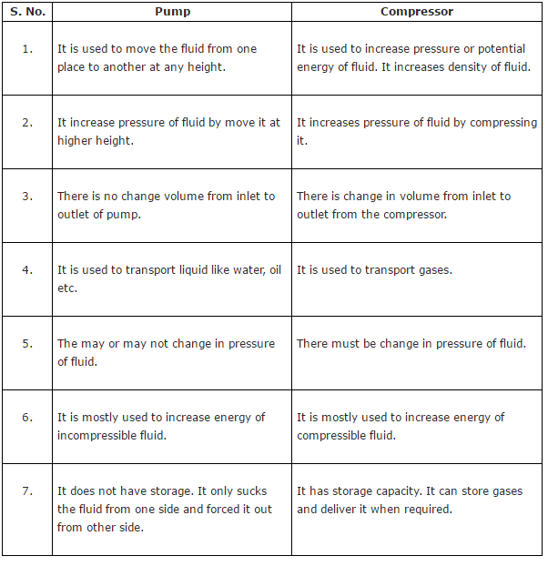
Difference between pump and compressor

The main difference between pump and compressor is that the pump is used to increase kinetic energy of fluid which further increases the elevation or pressure energy of it.  It moves the fluid from one place to another. But the compressor is mostly used to increase the potential energy (pressure energy) of fluid by pressuring it into a container. It is used to compress the fluid which increases its density and pressure. There are many other differences which are described below.

Difference between pump and compressor:


TIPS FOR DELIVERING SEMINARS

Seminars have always been an important aspect of education. It's an opportunity to either gain knowledge on an unknown topic or develop ideas regarding something you already know.It's a place where
you meet highly skilled persons and get to know their recent researches.You should attend at least a couple of seminars annually to keep yourself updated about the advancements taking place in your field. I've seen many people who keep avoiding seminars, although interested, just because they have never attended a seminar before. If this is your case, then I've only one thing to say "There's always a first time." Until and unless you attend a seminar, how can you overcome the fright?


Attending a seminar for the first time does not mean that you'll feel low or less confident than others. Here are a few tips that can make you seminar-ready. Here are a few tips that can help you get through a seminar and actually learn from it.

1. Know the Topic

Usually there are no prerequisites to attend a seminar but ideally you should know something about the seminar you're going to attend.First know the topic, yes the topic. I've seen a lot of people coming for a seminar and asking what the topic is! Know the meaning of each term related to the topic, like definitions, some dates, names of some important people in that field, etc. If you still have some time and energy left, know who the speaker is and his background. You can look for his area of study, some research works, etc. So now that you know what you need to know, I'll suggest you some ways by which you can know it.( I just hope I didn't confuse you. Oops, I did! )
Now-a-days you can literally find everything on the web,sometimes even the details you need about the speaker from his research works. Now that you have the basic knowledge of the topic, you can consult the faculties if you feel like. You can find lot of details online but only after talking to the profs you get to know which information is relevant for the seminar you're going to attend.Knowing more never goes in vain, but off course you wouldn't like to clog your mind with so many points. If you feel it hard to remember all the points, you can make short notes and take it with you to the seminar. Just make sure your focus is on the speaker as soon as the seminar starts and not on these notes.

2. A proper attire
it's never mandatory to wear formals for attending a seminar but avoid fancy dresses. Remember you're in the professional world, dress up like that. If you like make-ups go for it, but keep it light and simple. Just make sure you're comfortable with your look. In most of the cases, dressing up properly makes people feel confident.

3. Non-verbal communication
People can communicate a lot of things even without uttering a single word, through their body gestures, eye movement, etc. ere lies the importance of non-verbal communication. You can put a smile on you face just to show that you're there to learn and not to oppose the idea the speaker is going to present. Nodding your head sometimes during the speech can also communicate a lot about you. It means you're listening and understanding the topic as well.

4. Be attentive
It's not important to understand each and every part of the speech but at least you should get the essence of the speech. Just remember that the seminars are designed to provide you with a usable content on a variety of relevant subjects and keep you updated with the latest advancements in your field. So, try to gain as much knowledge as possible.

5. Asking Questions
It's the best way to get you ideas about the topic reviewed by an experienced person, you'll get to know if you're on the right track. Speakers also encourage questions and it's a way of learning on their part too. But whenever you ask a question, make sure you know exactly what you need to know clearly. Frame the question in your mind first, you certainly don't want to stumble while asking.
At this moment, I certainly don't want to demotivate you, just remember that silence is better than asking "silly questions".

So the next time you're going for a seminar, you already now what to do and how to do!

ADVANTAGES AND DISADVANTAGES OF WELDED JOINTS OVER RIVETED JOINTS

There are advantages as well as disadvantages of choosing welded joints over riveted joints. We shouldn’t join all surfaces by either by using welding processes or by using riveted joints. Depending upon need, one need to choose joining method.


Advantages:

  1. The welded structures are usually light in weight compared to riveted structures. This is due to the reason, that in welding, gussets or other connecting components are not used.
  2. The welded joints provide high efficiency, which is not possible in the case of riveted joints.
  3. Alterations and additions can be made easily in the existing structures.
  4. Welded structures are smooth in appearance, therefore it looks pleasing.
  5. A welded joint has a great strength. Often a welded joint has the strength of the parent metal itself.
  6. It is easily possible to weld any part of a structure at any point. But riveting requires enough clearance.
  7. The process of making welding joints takes less time than the riveted joints.
  8. Shape like cylindrical steel pipes can be easily welded. But they are difficulty for riveting.
  9. The welding provides very strong joints. which can’t be bended easily. This is in line with the modern trend of providing rigid frames.
  10. In welded connections, the tension members are not weakened as in the case of riveted joints.

Disadvantages:

  1. For making weld joints using weld symbols requires a highly skilled labour and supervision.
  2. Since there is an uneven heating and cooling in welding process during fabrication, therefore the members may get distorted or additional stresses may develop.
  3. Since no provision is kept for expansion and contraction in the frame, therefore there is a possibility of cracks developing in it.
  4. The inspection of defects in welding work is more difficult than riveting work.

Sunday, 23 October 2016

EXTRUSION AND ITS TYPE

Extrusion Processes:

Extrusion is the process of confining the metal in a close cavity and then allowing it to flow from only one opening , so that the metal will take the shape of the opening. The operation is identical to the squeezing of toothpaste out of the toothpaste tube.
By the extrusion process, it is possible to make component which have a constant cross section over any length as can be formed by the rolling process. Some typical parts can be extruded are shown:


Compexity of parts that can be obtain by extrusion is more than that of rolling, because the die required being very simple and easier to make. Also extrusion is a single pass process,unlike rolling the amount of reduction that si possible in extrusion is large. Generally brittle materials can be very easily extruded. It is also possible to produce sharp corners and different angles. It is possible to gets shapes with internal cavaties in extrusion by the use of spider die. Large diameters, thin walled , tubler products with execellent concentricity and tolerance charasitic can be produced.

Types of extrusion:
1: Direct extrusion or forward extrusion
2: Indirect extrusion or backward extrusion


Direct Extrusion or Forward Extrusion
The equipment consists of a cylinder or container into which the heated metal billet is loaded. One end of the container, the die plate with necessary opening is fixed. From the other end plunger or ram compresses the metal billet against the container walls and die plate, thus the forcing it to flow of metal in the forward direction through the die opening.

Acquiring the shape of the opening the extruded metal is then carried by the metal is then carried b the metal handling system as it comes out of the die. A dummy block which is a steel disc of about 40mm thick with a diameter slightly less than container is kept between the hot billet and the ram to protect it form heat and pressure. In direct extrusion, the problem of friction prevalent because of the relative motion between heated metal billet and cylinder walls. To reduce this friction lubricants are to be used. To reduce the damage to equipment, extrusion is finished quickly and the cylinder is cooled before further extrusion.

Indirect extrusion or backward extrusion
In order to completely overcome the problem, the backward hot extrusion as shown in figure, in this process the metal is confined fully by the cylinder, the ram which houses the die also compresses the metal against the container , forcing it to flow backward to the die in the hollow plunger or ram.
It is termed backward because of the opposite direction of the flow of the metal. Thus the billet in the container remains stationary and hence produce no friction. Also the extrusion pressure is not effected by the length. In the extrusion press since the friction is not loss. The figure of the backward extrusion is shown;

Saturday, 22 October 2016

TYPES OF MECHANICAL FORCES

A force exerted on a body can cause a change in either the shape or the motion of the body. The unit of force in SI system is the newton (N) and CGS system is dyne. No solid body is perfectly rigid and when forces are applied to it, changes in dimensions occur. Such changes are not always perceptible to the human eye since they are negligible. For example, the span of a bridge will sag under the weight of a vehicle and a spanner will bend slightly when tightening a nut. It is important for civil engineers and designers to appreciate the effects of forces on materials, together with their mechanical properties of materials.
There are three main types of mechanical forces that can act on a body. They are:
  1. Tensile force
  2. Compressive force and
  3. Shear force

1. Tensile force

Tensile force that tends to stretch a material, as shown in the figure 1 below.


Figure 1: Tensile force
For example,
  1. Rubber bands, when stretched, are in tension.
  2. The rope or cable of a crane carrying a load is in tension.
  3. When a nut is tightened, a bolt is under tension.
A tensile force will increases the length of the material on which it acts.


2. Compressive force

Compressive force that tends to squeeze or crush a material, as shown in the figure 2 below.

Figure 2: Compressive force
For example,
  1. A pillar supporting a bridge is in compression.
  2. The sole of a shoe is in compression.
  3. The jib of a crane is in compression.
compressive force will decrease the length of the material on which it acts.

3. Shear force

Shear force that tends to slide one face of the material over an adjacent face.

Figure 3: Shear force
For example,
  1. A rivet holding two plates together is in shear if a tensile force is applied between the plates as shown in Figure 3.
  2. A guillotine cutting sheet metal, or garden shears, each provide a shear force.
  3. A horizontal beam is subject to shear force.
  4. Transmission joints on cars are subject to shear forces.
shear force can cause a material to bend, slide or twist.

COMPARISON BETWEEN FIRE TUBE AND WATER TUBE BOILER

Comparison between Fire Tube and Water Tube Boiler can be done in 14 aspects. Those aspects are operating pressure, passage of material type in tubes, rate of steam generation, handling of load fluctuation, floor area requirement, efficiency, operator skills, design, maintenance cost are listed below in the tabular form.


Friday, 21 October 2016

MECHANICAL PROPERTIES OF MATERIALS

Mechanical properties helps us to measure how materials behave under a load. Mechanical properties of materials are mentioned below.

Elastic Material:

A material which regains its original size and shape on removal stress is said to be elastic stress.

Plastic material:

A material which can undergo permanent deformation without rupture aid to be plastic material. This property of the material is known as plasticity. Plasticity is important when a material is to be mechanically formed by causing the material to flow.

Ductile Material:

A material which an undergo considerable deformation without rupture is said to be ductile material. The major portion of deformation is plastic.

Brittle Material:

A material which ruptures with little or no plastic deformation is said to brittle materials.

Set of Permanent set:

The deformation or strain remaining in a body after removal of stress is known as permanent set. This is due to elastic property of material.

Elastic limit:

The greatest stress that a material can take without permanent set on the removal of stress is known as elastic limit.

Proportionality limit:

The greatest stress that a material can take without deviation from straight line between stress and strain is known as proportionality limit.

Endurance limit or Fatigue limit:

The greatest stress, applied infinite number of times, that a material can take without causing failure is known as endurance limit or fatigue limit.

Ultimate Strength:

The maximum stress material can take is known as ultimate strength. Ultimate strength is equal to maximum load divided by original area of cross section.

Modulus of Resilience:

The energy stored per unit volume at the elastic limit is known as modulus of resilience.

Modulus of Toughness:

The amount of work required per unit volume to cause failure, under static loading, is called modulus of toughness.

Modulus of Rupture:

The ultimate strength in flexure or torsion is known as modulus of rupture.

Strain hardening:

The increase in strength after plastic zone due to rearrangement of molecules in the material.

Proof stress:

The stress which is just sufficient to cause a permanent set(elongation) equal to a specified percentage of the original gauge length.

Elastic Strain:

Elastic strain is a dimensional change that occur in a material due to the application of loads and disappears completely on the removal of the loads.

Plastic Strain:

It is a dimensional change that occurs in a material due to application of the loads and does not disappear after the removal of the loads.

Ductility and malleability:

The plastic response of material to tensile force is known as ductility and plastic response to compression force is known as malleability. The elongation and reduction of area of test piece tested to failure in tension are generally taken as measures of ductility of material.

Creep:

The long term deflection due to sustained (constant) loads.

Factor of Safety:

Factor of safety is defined as follows
For Ductile materials,
F.O.S = yield stress / working stress
For Brittle materials,
F.O.S = ultimate stress / working stress

Margin of Safety:

Margin of safety = Factor of safety – 1

LEARN HOW TO READ TYRE SPECIFICATIONS

The sidewall of tyre provides the information about the tyre including the specifications, the brand, etc. All the codes on tyres are standardized and recognized by all tyre manufacturers worldwide


Meaning of codes marked on tyres:
  1. Tyre width (in mm)
  2. Aspect Ratio
  3. Rim Diameter (in inches)
  4. Load Index
  5. Speed rating
Specifications of tyre marked on sidewall on above image as 235/45R17 97W
The ‘235’ indicates the section width of the tyre in millimeters.
The ’45’ tells the ‘profile’ of the tyre, or the width of the tyre compared to its height. It is expressed in percentage. (45%, in this case).
The ‘R17′ indicates the size (in inches) of the wheel rim to which the tyre is designed to be fitted.
The ’97’ indicates the tyre’s load index, and
The ‘W’ denotes the speed rating.
Load Index:
Load index corresponds to the load capacity . Commonly chosen load index values of automobiles are shown below in image.

Speed Rating:
The Speed rating of a tyre is the maximum speed at which the tyre can carry a load corresponding to its load index is an assigned letter ranging from J to Z that corresponds to the reference maximum speed at the associated load index. Refer to the speed rating table below.

Wednesday, 19 October 2016

CAM FOLLOWER AND THEIR TYPE

cam is a rotating or sliding piece in a mechanical linkage that drives a mating component known as a follower. From a functional viewpoint, a cam-and-follower arrangement is very similar to the linkages. The cam accepts an input motion (rotary motion or linear motion) and imparts a resultant motion (linear motion or rotary motion) to a follower.

Cam Nomenclature

FIGURE 1 CAM nomenclature
Cam profile: Cam profile is outer surface of the disc cam.
Base circle: Base circle is the smallest circle, drawn tangential to the cam profile.
Trace point: Trace point is a point on the follower, trace point motion describes the movement of the follower.
Pitch curve: Pitch curve is the path generated by the trace point as the follower is rotated about a stationery cam.
Prime circle: Prime circle is the smallest circle that can be drawn so as to be tangential to the pitch curve, with its centre at the cam centre.
Pressure angle: The pressure angle is the angle between the direction of the follower movement and the normal to the pitch curve.
Pitch point: Pitch point corresponds to the point of maximum pressure angle.
Pitch circle: A circle drawn from the cam center and passes through the pitch point is called Pitch circle.
Stroke: The greatest distance or angle through which the follower moves or rotates.

Types of Cams


Various custom cams
Cams can be classified into the following three types based on their shapes. They are:
  1. Plate or disk cams: Plate or disk cams are the simplest and most common type of cam. A plate cam is illustrated in figure 3 (a). This type of cam is formed on a disk or plate. The radial distance from the center of the disk is varied throughout the circumference of the cam. Allowing a follower to ride on this outer edge gives the follower a radial motion.
  2. Cylindrical or drum cam: A cylindrical or drum cam is illustrated in figure 3 (b). This type of cam is formed on a cylinder. A groove is  cut into the cylinder, with a varying location along the axis of rotation. Attaching a follower that rides in the groove gives the follower motion along the axis of rotation.
  3. Linear cam: A linear cam is illustrated in figure 3 (c). This type of cam is formed on a translated block. A groove is cut into the block with a distance that varies from the plane of translation. Attaching a follower that rides in the groove gives the follower motion perpendicular to the plane of translation.

FIGURE 3 Cam types

Types of Followers

Followers are classified based on their motion, position and shape. The details of followers classifications are shown in the figure 4 and discussed below

FIGURE 4 Follower types
1. Based on Follower Motion
Based on the follower motion, followers can be classified into the following two categories:
(i). Translating followers are constrained to motion in a straight line and are shown in figure 4 (a) and 4 (c).
(ii). Swinging arm or pivoted followers are constrained to rotational motion and are shown in figure 4 (b) and 4 (d).
2. Based on Follower Position
Based on the follower position, relative to the center of rotation of the cam, is typically influenced by any spacing requirements of the machine. The position of translating followers can be classified into the following two categories:
(i). An in-line follower exhibits straight-line motion, such that the line of translation extends through the center of rotation of the cam and is shown in figure 4 (a).
(ii). An offset follower exhibits straight-line motion, such that the line of the motion is offset from the center of rotation of the cam and is shown in figure 4 (c).
In the case of pivoted followers, there is no need to distinguish between in-line and offset followers because they exhibit identical kinematics.
3. Based on Follower Shape
Finally, the follower shape can be classified into the following four categories:
(i). A knife-edge follower consists of a follower that is formed to a point and drags on the edge of the cam. The follower shown in figure 4 (a) is a knife-edge follower. It is the simplest form, but the sharp edge produces high contact stresses and wears rapidly. Consequently, this type of follower is rarely used.
(ii). A roller follower consists of a follower that has a separate part, the roller that is pinned to the follower stem. The follower shown in figure 4 (b) is a roller follower. As the cam rotates, the roller maintains contact with the cam and rolls on the cam surface. This is the most commonly used follower, as the friction and contact stresses are lower than those for the knife-edge follower. However, a roller follower can possibly jam during steep cam displacements.
(iii).  A flat-faced follower consists of a follower that is formed with a large, flat surface available to contact the cam. The follower shown in figure 4 (c) is a flat-faced follower. This type of follower can be used with a steep cam motion and does not jam. Consequently, this type of follower is used when quick motions are required. However, any follower deflection or misalignment causes high surface stresses. In addition, the frictional forces are greater than those of the roller follower because of the intense sliding contact between the cam and follower.
(iv).  A spherical-faced follower consists of a follower formed with a radius face that contacts the cam. The follower shown in figure 4 (d) is a spherical-face follower. As with the flat-faced follower, the spherical- face can be used with a steep cam motion without jamming. The radius face compensates for deflection or misalignment. Yet, like the flat-faced follower, the frictional forces are greater than those of the roller follower.

Monday, 17 October 2016

AUTOMOTIVE NIGHT VISION SYSTEM

The term “automotive night vision” refers to a number of systems that help increase driver awareness when it’s dark out. These systems extend the perception of the driver beyond the limited reach of the headlights through the use of thermographic cameras, infrared lights, heads up displays, and other technologies. Since automotive night vision can alert drivers to the presence of potential hazards before they become visible, these systems can help prevent accidents.

How Does Night Vision Work in Cars?

Automotive night vision systems are broken into two basic categories, which are referred to as active and passive. Active night vision systems uses infrared light sources to illuminate the darkness, and passive systems rely on the thermal radiation that is emitted from cars, animals, and other potential hazards. The systems both rely on infrared data, but each one has its own benefits and drawbacks.

Active Automotive Night Vision Systems

Active systems are more complex than passive systems because they use infrared light sources.
Since the infrared band falls outside the visible spectrum, these light sources don’t cause oncoming drivers to suffer from temporary night blindness like high beam headlights can. That allows the infrared lights to illuminate objects that are significantly further away than headlights are able to reach.
Since infrared light isn’t visible to the human eye, active night vision systems use special cameras to relay the extra visual data. Some systems use pulsed infrared lights, and others use a constant light source. These systems don’t work very well in adverse weather conditions, but they do provide high contrast images of vehicles, animals, and even inanimate objects.

Passive Automotive Night Vision Systems

Passive systems don’t use their own light sources, so they rely on thermographic cameras to detect thermal radiation. This tends to work very well with animals and other vehicles since they emit a lot of thermal radiation. However, passive systems have trouble picking up inanimate objects that are about the same temperature as the surrounding environment.
The range of passive night vision tends to be significantly higher than the range of active night vision, which is due to the limited power of the light sources used by the latter systems. The image quality produced by the thermographic cameras also tends to be poor when compared to active systems, and they don’t work very well in warm weather.

How Does Infrared or Thermographic Information Help Me See?

There are a number of types of night vision displays that can relay infrared or thermographic information to the driver. The earliest night vision systems used heads up displays, which projected warnings and alerts on the windshield within the driver’s field of vision. Other systems use an LCD that's mounted on the dash, in the instrument cluster, or integrated into the head unit.

AIR BAGS

Air Bags:-
An airbag is a type of vehicle safety device and is an occupant restraint system. The airbag module is designed to inflate extremely rapidly then quickly deflate during a collision or impact with a surface or a rapid sudden deceleration. 

The purpose of the airbag is to provide the occupants a soft cushioning and restraint during a crash event to prevent any impact or impact-caused injuries between the flailing occupant and the interior of the vehicle. The airbag provides an energy absorbing surface between the vehicle's occupant and a steering wheel, instrumental panel, A-B-C- structural body frame pillars, headliner and windshield/windscreen.

There are three parts to an airbag that help to accomplish this feature:
>The bag itself is made of a thin, nylon fabric, which is folded into the steering wheel or dashboard or, more recently, the seat or door.
>The sensor is the device that tells the bag to inflate. Inflation happens when there is a collision force equal to running into a brick wall at 10 to 15 miles per hour (16 to 24 km per hour). A mechanical switch is flipped when there is a mass shift that closes an electrical contact, telling the sensors that a crash has occurred. The sensors receive information from an accelerometer built into a microchip.

>The airbag's inflation system reacts sodium azide (NaN3) with potassium nitrate (KNO3) to produce nitrogen gas. Hot blasts of the nitrogen inflate the airbag.