Thursday, 29 September 2016

ELECTRIC RESISTANCE WELDING

Electric Resistance Welding
It is a type of pressure welding. It is used for joining pieces of sheet metal or wire. The welding heat is obtained at the location of the desired weld by the electrical resistance through the metal pieces to a relatively short duration, low voltage, high ampere electric current.
The amount of current can be regulated by changing the primary turns of the transformer. When the area to be welded is sufficiently heated, the pressure varying from 25MPa to 55MPa is applied to the joining area by suitable electrodes until the weld is solid. The various types of electric resistance welding are as follows:

(1) Spot welding
It is used for welding lap joints, joining components made from plate material having 0.025 to 1.25 mm in thickness. The plate to be joined together are places between the two electrode tips of copper or copper alloy.
Spot Welding

(2) Roll spot and seam welding
When the spot welds on two over lapping pieces of metal are spaced, the process of welding is known as roll spot welding. If the spot welds are sufficiently made close, then the process is called seam welding. This process is best for metal thickness ranging from 0.0.25 to 3 mm.

Seam Welding

(3) Projection welding
It is similar to spot welding except that one of the metal pieces to be welded has projections on its surface at the points, Where the welds are to be made. In other words it is a multi spot welding process.


(4) Butt welding
The butt welding is of two type :
·        Upset butt welding
·        Flash butt welding
The upset butt welding is especially adopted to rods, pipes and many other components of uniform sections. The flash butt welding is extensively used in the manufacture of steel containers and in the welding of mild steel shanks to high speed drills and reamers.


10 THINGS TO KNOW ABOUT INDUS WATER TREATY

10 things to know about Indus Water Treaty
The Indus Waters Treaty 1960, which settled the sharing of the Indus waters, is internationally regarded as an example of successful conflict-resolution between two countries otherwise locked in a bad relationship.
For 56 years, both India and Pakistan are peacefully sharing the water of Indus and its tributaries, thanks to The Indus Water Treaty.

At a time when States within India are unable to find an amicable solution to sharing water from rivers that flow between them, India and Pakistan are living examples of how water resources can be shared through legal frame work.
For 56 years, both India and Pakistan are peacefully sharing the water of Indus and its tributaries, thanks to The Indus Water Treaty.
1
The Indus Waters Treaty was signed on September 19, 1960 by the then Prime Minister Jawaharlal Nehru and Pakistan's President Ayub Khan. 
2
It was brokered by the World Bank.
3
The treaty administers how river Indus and its tributaries that flow in both the countries will be utilised.
4
According to the treaty, Beas, Ravi and Sutlej are to be governed by India, while, Indus, Chenab and Jhelum are to be taken care by Pakistan.
5
However, since Indus flows from India, the country is allowed to use 20 per cent of its water for irrigation, power generation and transport purposes.
6
A Permanent Indus Commission was set up as a bilateral commission to implement and manage the Treaty. The Commission solves disputes arising over water sharing.
7
The Treaty also provides arbitration mechanism to solve disputes amicably.
8
Though Indus originates from Tibet, China has been kept out of the Treaty. If China decides to stop or change the flow of the river, it will affect both India and Pakistan.
9
Climate change is causing melting of ice in Tibetan plateau, which scientists believe will affect the river in future.
10
It maybe noted that both India and Pakistan are still at loggerheads over various issues since Partition, but there has been no fight over water after the Treaty was ratified.

LIQUID PROPELLANT ROCKET ENGINE

   A liquid-propellant rocket or liquid rocket is a rocket engine that uses liquid propellants. Liquids are desirable because
their reasonably high density allows the volume of the propellant tanks to be relatively low, and it is possible to use lightweight centrifugal turbopumps to pump the propellant from the tanks into the combustion chamber, which means that the propellants can be kept under low pressure. This permits the use of low-mass propellant tanks, resulting in a high mass ratio for the rocket.
There are two types of liquid propellents :-
a)      Monopropellants
b)      Bipropellants
a)      Monopropellant
A liquid propellant which contains both fuel and oxidizer in a single chemical is known as monopropellant. It stable at ambient conditions and liberates thermo-chemical energy on heating. Monopropellants have been widely used in solid propellant rockets.
Examples : Nitro glycerin, nitro methane, Hydrogen peroxide, Hydrazine
b)     Bipropellants
If the fuel and oxidizer are different from each other in its chemical nature then the propellant is called bipropellant. Bipropellants have been widely used in liquid propellant rocket system.

PROPERTIES OF LIQUID PROPELLANTS

  • Propellant should have high calorific value
  • Its density should be high
  • It should have low values of vapor pressure and viscosity
  • It should have higher specific heat and thermal conductivity
  • Products of combustion should have low molecular weight to produce high jet velocity
  • It should be non corrosive and non reactive with components of the engine
  • It should not be poisonous and hazardous
  • It should be cheap and easily available
  • Energy released during combustion per unit mass of the propellant combination should be high
  • It should be easily ignitable

LIQUID PROPELLANT ROCKET ENGINE
Construction
  1. Liquid fuel(refined petrol, liquid hydrogen, hydrazine etc) and liquid oxygen are used in this engine
  1. Liquid fuel and liquid oxygen are stored separately in two different tanks
  2. Preheater is used to heat the fuel and oxidizer
  3. Nozzle is used to increase the velocity and decrease the  pressure of the gases
  4. The construction of liquid propellant rocket engine is shown in figure.


Working
  1. Liquid fuel and liquid oxygen are pumped separately into a combustion chamber through control valves.
  1. Since the liquid fuel and liquid oxygen are stored at  very low temperature , they are preheated in the preheated to a  suitable temperature
  2. The preheater fuel-oxidizer mixture is injected into the combustion chamber through suitable injector and combustion takes place.
  3. When the combustion takes place in the combustion chamber , very high pressure and temperature gases are produced
  4. he highly heated products of combustion gases are then allowed to expand in nozzle section.
  5. In the nozzle, pressure energy of the gas is converted into kinetic energy. So the gases coming out from the unit with the very high velocity.
  6. Due to high velocity of  gases coming out from the unit , a force or thrust is produced in the opposite direction. This thrust propels the rocket.
Advantages
  1. Liquid propellant engines can be reused after recovery. So it is economical .
  2. Combustion process is controllable.
  3. Speed regulation is possible
  4. High specific impulse
  5. More economical for long range operation
  6. Malfunctions and accidents can be rectified at any stage
Disadvantages
  1. It’s construction is more complicated compared to solid propellant rock
  2. There are additional handling and safety problems if the propellants are poisonous and corrosive
  3. Manufacturing cost is high
  4. High vibration
  5. Size and weight of the engine is more compared to solid propellant rockets
Any liquid propellants can exist in liquid state at very low temperature. So proper insulation is needed

CONTINUOUS VARIABLE TRANSMISSION

CVT is an automatic transmission that can select any desired drive ratio within its operating range. Unlike a conventional four or five-speed transmission, CVT is an infinite speed ratio transmission.

In the manual gearbox one problem is faced that the one speed ratio is not fully efficient in the desire range. So the manufactures have to work on a new system which can obtain infinite speed ratio and there is one unique speed ratio for one speed. This is the basic idea of CVT. 

Principle of CVT Transmission:

As an ordinary gear box CVT also works on the same gearing principle that when we attached a big driving gear to one small driven gear we obtain high torque and vice versa. But the CVT does not used gear to obtain speed ratio of transfer power. The other power transmission system belt drive used in CVT can change its diameters.  
There are three main component of CVT which make is able to obtain infinite speed ratio transmission. These are a variable input driving pulley, a variable output driven pulley and a metallic belt.
Apart from these, there are also various microprocessors and sensors and even epicyclic gearing and clutch. Both the driving and driven pulleys are of variable diameter type. Each pulley is made of two 20 degree cones facing each other. A belt is there in the groove between the two cones. The belts are specially constructed to provide for the required flexibility.
The driving pulley is connected to the engine crankshaft while the driven pulley transfers motion to the drive shaft. When the two cones of the pulley are close together, the belt rides higher in the groove and the pulley diameter apparently increases, whereas the belt rides lower in the groove, making the effective diameter decrease, when the two cones of the pulley are far apart. These cones are moved closer or far apart using hydraulic pressure, centrifugal force or spring tension.
CVT  : Continuously Variable Transmission

 If diameter of driving pulley increases, the diameter of driven pulley decreases, and vice versa. This is done to keep the belt always tight. As the pulley change their diameter relative to each other, infinite number of gear ratio are obtained. For low gearing the diameter of small on the driving pulley and large on the driven pulley and for high gearing vice versa.
A conventional CVT uses the information from engine management ECU to determine the torque being delivered by the engine and accordingly the pressure exerted on the belt to avoid slipping. Further the drive is transmitted separately to forward gears and to reverse, through two multiple clutches. There are also two small hydraulic chambers for moving the variator pulleys instead of one larger chamber in case of conventional CVT, this reduces the power consumed.

Advantages and Disadvantages of CVT Transmission:


Advantages:

1. It provides the smoother ride compare to conventional gearing system.
2. It increases the fuel economy of vehicle by deliver optimum power range under all conditions.
3. It eliminates gear hunting while moving up and incline.
4. It decreases emissions due to better engine control under all conditions.

Disadvantages:

1. Torque handling capacity of a CVT is limited by the strength of the belt.
2. CVT has much shorter life compare to conventional gearing system.
3. CVT need large central distance which cannot be provided in inline configuration.


The CVT are already used by some manufactures like Nissan to obtain high efficiency. We can say that this technology continues growing and manufactures are looking forward with it. User loves them because of its efficiency and smooth riding.  This system is also ecofriendly so the manufactures and government promoting it and soon it will adopted by most of manufactures. Audi’s Multitronic is also example of it. 

Wednesday, 28 September 2016

WHY DIESEL ENGINES ARE MORE EFFICIENT THAN PETROL ENGINE

WHY DIESEL ENGINES ARE MORE EFFICIENT THAN PETROL ENGINE 
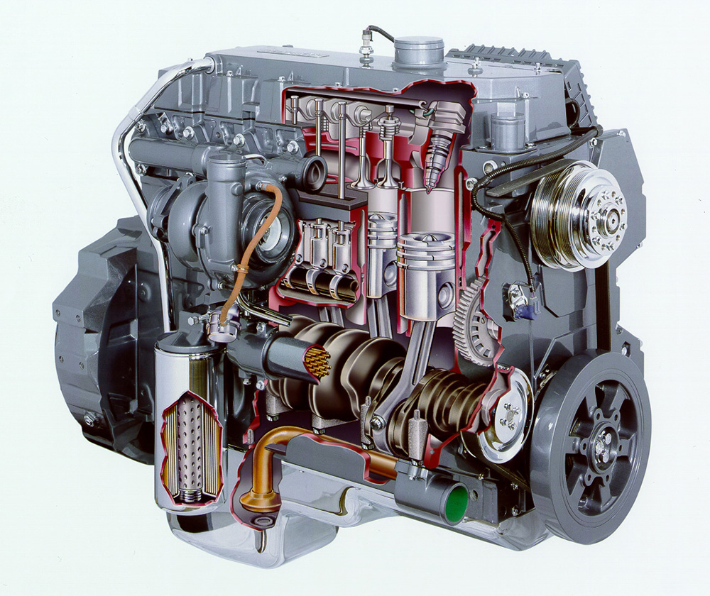
You know that diesel engine is the most appropriate choice of the engineers when it comes to drive heavy automobile like trucks, aircraft, ships etc. But what makes it so torque, is it the engine design, working cycle or something else. We will look towards a deep analysis to answering these questions.
Image result for diesel engine cutaway
Following are the reasonable points that conclude the high torque and efficiency of diesel engine.
  • Diesel engine uses simple mechanism for combustion unlike in gasoline engine. Removal of ignition system not only makes the mechanism simpler but also reduces the risk of improper combustion due to damage in ignition system. In short burning of the fuel is easy and always accessible. This results in higher efficiency diesel engine.
  • Diesel fuel is a heavier hydrocarbon in which carbon and hydrogen are strongly bonded with each other. And when energy is supplied in form of heat it gets explode releasing much higher energy then gasoline. In short diesel fuel has higher energy density then gasoline which results in huge explosion.
  • One more factor for higher efficiency in diesel engine is its property of lubrication. Although all fuel has property of lubrication but diesel fuel has much higher lubrication then gasoline fuel.
  • The compression ratio is much higher in diesel as compared to gasoline because in diesel engine air is alone compressed inside the cylinder and it’s a known fact that gas easily compresses then liquid. This is not so in gasoline engine because air-fuel mixture is compressed inside the cylinder. This higher compression gives higher heat and simultaneously higher torque.
  • We can’t use Carnot cycle to get 100% efficiency but can use its principle to attain maximize efficiency. In diesel engine heat is added at constant pressure which results in higher utilization of heat energy to get maximize work output.
These were the advantageous features of diesel engine but it has some demerits as well like it releases highly toxic gasesnoisyhigher maintenance cost and starting problem (now starting problem is eliminated by using a bulb nearby to the cylinder) to heat the engine before ignition. And it is costlierthan gasoline engine but with optimum operation and good maintenance resolve all these problems.

BROACHING OPERATION

Broach:
A broach is a multi point cutting tool having a series of cutting teeth or edges which gradually increase in size from the starting or entering end to the rear end. Broaches are used for machining either external or internal surfaces. These surfaces may be produced flat or circular. In broaching, the broach is pushed or pulled over or through a surface of work piece, Each tooth of the tool. A thin slice from surface broaching of inside surface is called internal or hole broaching and outside surfaces is called surface broaching.

Detail of an internal or hole broach:
A typical broach is shown in figure.
It is used to machine an internal hole. The broach is gripped by puller at the shank end. The front rake angle refers a rake angle of a single point cutting tool and back of the angle (relief angle) is provided to prevent rubbing of the tool with the work piece.


High speed steel (Hss) material is widely used to make the broach. It is also raised carbide of disposable inserts or sometime used for cutting edges then machining cost iron parts, which requires close tolerance. Carbide tools are also used to an advantage  on steel cutting. A broach may be either assembled or built up form shells.

Monday, 26 September 2016

MULTIPLE QUESTIONS OF FLUID MECHANICS WITH ANSWERS

MULTIPLE QUESTIONS OF FLUID MECHANICS:-

1-Bernoulli’s equation cannot be applied when the flow is
(A) rotational
(B) turbulent
(C) unsteady
(D) all of the above(Ans: D)


2-Streamline and equipotential lines in a flow field
(A) are parallel to each other
(B) are identical to each other
(C) are perpendicular to each other
(D) intersect at acute angles(Ans: C)
3-Relative density of mercury is
(A) 1
(B) 9.8
(C) 13.6
(D) 1000(Ans: C)
4-A Newtonian fluid is defined as the fluid which
(A) Obeys Hook’s law
(B) Is compressible
(C) Obeys Newton’s law of viscosity
(D) Is incompressible(Ans: C) 
5-If the Reynolds number is less than 2000, the flow in a pipe is
(A) Turbulent
(B) Laminar
(C) Transition
(D) None of the above(Ans: B)
 6-A flow is called super-sonic if the
(A) velocity of flow is very high
(B) discharge is difficult to measure
(C) Mach number is between 1 and 5
(D) Mach number is less than 1(Ans: C)
 7-The unit of pressure one bar is
(A) 1 Pascal
(B) 1 kilo Pascal
(C) 100 kPascal
(D) 1000 kPascal(Ans: C)
 8-The dynamic viscosity of a liquid is 1.2 × 10⁻⁴ Ns/m2, whereas, the density is 600 kg/m3. The kinematic viscosity in m2/s is
(A) 72 × 10-3
(B) 20 × 10-8
(C) 7.2 × 10³
(D) 70 × 106
(Ans: B)
9-The location of the centre of pressure over a surface immersed in a liquid is
(A) always above the centroid
(B) will be at the centroid
(C) will be below the centroid
(D) for higher densities it will be above the centroid and for lower densities it will be below the centroid(Ans: C)
 10-The continuity equation is the result of application of the following law to the flow field
(A) First law of thermodynamics
(B) Conservation of energy
(C) Newtons second law of motion
(D) Conservation of mass(Ans: D)
 11-Reynolds number signifies the ratio of
(A) gravity forces top viscous forces
(B) inertial forces to viscous forces
(C) inertia forces to gravity forces
(D) buoyant forces to inertia forces(Ans: B)
 12-In pipe flow the critical Reynolds number is about
(A) 640
(B) 5 × 10⁵
(C) 2000
(D) 64000(Ans: C)
 13-Anemometer is used to measure
(A) Velocity
(B) Pressure
(C) Viscosity
(D) Density(Ans: A)
 14-Property of fluid that describes its internal resistance is known as:
(A) Viscosity
(B) Friction
(C) Resistance
(D) Internal energy(Ans: A)
 15-Which fluid does not experience shearing stress during flow?
(A) Pseudoplastic
(B) Dilatant
(C) Newtonian
(D) Inviscid(Ans: D)
 16-Stress strain relationship for Newtonian fluid is
(A) Parabolic
(B) Hyperbolic
(C) Linear
(D) Inverse type(Ans: C)