Sunday, 31 July 2016

ELECTRIC DISCHARGE MACHINING

Introduction:-
In Electric Discharge Machining process an arc is produced when two current-carrying wires are short-circuited. During this machining process,
a small portion of metals is also eroded away, leaving a small cater. this phenomenon is used in electric discharge machining (EDM). EDM machining process is also known as spark erosion machining.
EDM involves a controlled erosion of electrically conductive materials by the initiation of electrically conductive materials by the initiation of rapid and repetitive spark discharges between the tool and workpiece separated by a small gap. Each electrical spark produces sufficient heat to melt a portion of the workpiece and usually, some of the tooling materials also. Due to rapid heating, the dielectric fluid evaporates in the arc gap which increases the resistance until the arc is interrupted. The associated shock wave and flowing dielectric fluid remove the gas bubbles which later collapse.
Electro chemical dissolution is based on the Faraday’s laws, stated as follows:
The amount of electrochemical dissolution or deposition(m) is proportional to amount of charge (Q) passed.
The amount of material deposited or dissolved further depends on electrochemical equivalence (ECE) of the material, that is, the ratio of the atomic weight (A) and velocity (v).

Summary of EDM characteristics:

  • Mechanics of material removal rate: Melting and evaporation aided by cavitations (spark erosion).
  • Medium: Dielectric fluid (generally kerosene).
  • Tool material: Cu, Brass, Cu-W Alloy, Ag-W-Alloy, Graphite.
  • Wear Ratio: 0.1 to 10.
  • Maximum material removal rate (MRR) is 5× 103 mm3/min.
  • Specific power consumption: 1.8 W/mm3/min.
  • Gap between work piece and tool is 10 to 125 µm.

Advantages:

  • L/D ratio as high as 20 can be achieved.
  • There is no contact between tool and workpiece so no forces acting in machining. So no residual stresses are generated in machining.
  • Out of all the unconventional machining methods, EDM is the one which gives highest MRR,
  • Melting and evaporation is the mechanism for chip formation, the mechanical properties of work piece material will not affect the material removal rate (MRR).
  • Surface finish produced will be better.

Disadvantages:

  • Used only for electrically conductive material.
  • Electrode wear is more.
  • Re-hardening occurs due to heat generated during machining.
  • Not possible to make exact square corners.

Applications of Electric Discharge Machining process:

  • Blind cavities and narrow slots in dies, minimum diameter hole can be produced is 0.13mm.
  • L/D ratio is as high as 20 can be done. So, due to this, EDM is particularly useful in machining of small holes, orifices, slots in diesel fuel injection nozzles, airbrake valves and aircraft engines etc.

Friday, 29 July 2016

Check out the Why the Power Of Engines Are Measured In “Horsepower”

We come across many physical quantities in our day-to-day life. Like we measure the distance in Metre, force in Newton, temperature in Celsius. Generally,
these units are named after the scientists who discovered them or who worked extensively in that particular field. But when it comes to Power, it is measured in “horsepower”. So have you ever wondered why horsepower is used as the measurement of Power?


Here’s the reason behind it:

In 1781, James Watt introduced an enhanced steam engine. It saved up to 75% of the fuel when compared to that of the existing Newcomen engine. But at that time a majority of consumers used draft horses for their mechanical needs. In order to explain to people that his engine was more productive than draft horses, Watt came up with a solution. He wanted to bring out a comparison between his engine & draft horses. With a series of experiments, James Watt calculated that a typical draft horse could do nearly 33,000 foot-pound of work (i.e to lift a 33,000-pound weight in 1 foot) in a single minute. Thus, he gave birth to a new unit – horsepower. 
Mathematically horsepower is defined as follows:
1 horsepower = 33,000-foot pounds of work done per minute.
Even though the value of horsepower was not clear, it didn’t stop buyers from buying Watt’s 5 horsepower engine. In simpler words, his engine can do a work approximately equivalent to 5 horses. The term horsepower is still used as a supplementary unit to the output power of turbines, piston engines etc.
3

COMPARISON BETWEEN MACPHERSON AND DOUBLE WISHBONE SUSPENSION SYSTEM

Two of the most popular suspensions systems for passenger cars today are the double wishbone suspension system and the MacPherson’s
strut suspension system. While it is more usual to see the double wishbone system at the rear end of the car,  MacPherson’s solution normally finds its place at the front end of the car. Both types of suspensions have their own sets of benefits and limitations, thus let us look at both the advantages and disadvantages of both systems, starting with the simpler of the two, the MacPherson struts.

MacPherson Struts- The struts are designed with more simplicity, and thus takes up less space horizontally. As a result, passengers get more compartment place in the car. They also display low un-sprung weight, an advantage that reduces the overall weight of the vehicle as well as increases the car’s acceleration. Lower un-sprung weight also makes your ride more comfortable. Another major advantage of this system is its ease of manufacturing as well as low cost of manufacture compared to other stand-alone suspension systems. Without an upper arm, the suspension system designers can directly block vibration from reaching the passenger compartment.
Nevertheless, the MacPherson struts come with their own drawbacks. Being a long, vertical assembly, you would encounter difficulties if you lower your car as they may be collision with the structure of your car. Thus they do not work well with racing cars that are normally lowered. The MacPherson struts also have problems working with wider wheels that have increased scrub radius, where you would need extra effort to navigate your car in this situation. There is also the problem with the small camber change with vertical movement of the suspension, which could mean the tires have less contact with the road during cornering. This could reduce handling abilities of your vehicle.

Double Wishbone Suspension System- One of its primary benefits is the increase of negative chamber as a result of the vertical suspension movement of the upper and lower arms. This translates to better stability properties for the car as the tires on the outside maintain more contact with the road surface. Handling performance also increases. The double suspension system is much more rigid and stable than other suspension systems, thus you would realize that your steering and wheel alignments are constant even when undergoing high amounts of stress.

Moving on to the drawbacks of the double wishbone suspension system, it is normally bugged by cost issues as it is a more complicated design to produce. There are many parts to the system, and thus every time any of these malfunction of fail, your whole system fails. Repair, modification and maintenance costs and complexities for double wishbone suspension systems are normally higher due to these reasons. This suspension system also proves to be flexible for design engineers, as the arms of the system can be fixed at different angles to the surface, parameters such as camber gain, roll center height and swing arm length can be determined and designed flexibly to suit and road surface in condition.

As we have seen, both suspension systems have their own plus points and limitations. To conclude, double wishbones may perform better, but the MacPherson struts would prove to be more affordable in the long run.

HOW DOES GEAR RATIO EFFECT TORQUE?

First....What is torque?:

Torque is a twisting force- (it doesn't do any 'work' itself- it is simple an application of energy). 


Work (or 'stuff') happens, when torque is applied and movement occurs.
"Torque is a force that tends to rotate or turn things. You generate a torque any time you apply a force using a wrench. Tightening the lug nuts on your wheels is a good example. When you use a wrench, you apply a force to the handle. This force creates a torque on the lug nut, which tends to turn the lug nut. 

English units of torque are pound-inches or pound-feet; the SI unit is the Newton-meter. Notice that the torque units contain a distance and a force. To calculate the torque, you just multiply the force by the distance from the center. In the case of lug nuts, if the wrench is a foot long, and you put 200 pounds of force on it, you are generating 200 pound-feet of torque. If you use a two-foot wrench, you only need to put 100 pounds of force on it to generate the same torque." 

In summary:
Torque equals Force multiplied by Distance

How does gear ratio affect Torque?
Simply put, torque at work (such as at a wheel) is your motor's torque times your gear ratio.
Motor Torque x gear ratio = torque at the wheel

Lets say we have a 10rmps motor that is capable of 5 oz Torque (we know this from our motor spec.)

Lets say we have 2 gears. Our input gear (attached to our motor) has 10 teeth Our output gear has 50 teeth

Our Gear ratio is 5:1

Motor Torque x gear ratio = torque at the wheel

5oz x 5:1 = 25 oz

What if our gear ratio were 1:3 ?

5oz x 1:3 = 1.6oz

TYPES OF GEAR WITH THEIR APPLICATIONS

Gears

Gears are Power transmission elements. It is the Gears that decides the torque, speed and direction of rotation of all the driven machine elements.
Broadly speaking, Gear types may be grouped into five major categories. They are Spur, Helical, Bevel, Hypoid, and Worm. A lot of intricacies are there in the different types of gears. Actually The choice of gear type is not a very easy process. It is dependent on a number of considerations. Factors that go into it are physical space and shaft arrangement, gear ratio, load, accuracy and quality level.

Types of Gears

Types of Gears


A number of gears are manufactured using different materials and with different performance specifications depending on the industrial application. These gears are available in a range of capacities, sizes and speed ratios, but the main function is to convert the input of a prime mover into an output with high torque and low RPM. These range of gears find use in almost every industry right from agriculture to aerospace, from mining to paper and pulp industry. Some of the popular types of gears in use are :

Spur Gears

Spur Gear


Spur gears are straight-toothed gears having radial teeth used to transmit power and motion between parallel axes. These gears are widely used for speed increase or reduction, high torque, resolution for positioning systems.

These gears can either be mounted on a hub or a shaft. The gears are available in different size, design, shape and also offer a variety of features and functions to cater to different industrial requirements.

Materials Used
Spur gears are fabricated from superior quality materials, like: 

  • Metal- steel, cast iron, brass, bronze and stainless steel.
  • Plastic- acetal, nylon and polycarbonate.
Materials used to manufacture these gears are used keeping in mind certain factors including design life, power transmission requirements, noise generation.

Important Specifications to be Considered 

  • Gear center
  • Bore diameter
  • Shaft diameter
Use of Spur Gears
These gears find wide application in a number of fields including : 

  • Automobiles
  • Textiles
  • Industrial engineering

Bevel Gears

Bevel Gear


Bevel gears are mechanical devices used for transmitting mechanical power and motion. These gears are widely used for transmitting power and motion between nonparallel axes and are designed to transmit motion between intersecting axes, generally at right angles. The teeth on bevel gear can be straight, spiral or hypoid. The gears are suitable when the direction of a shaft's rotation needs to be changed.

Materials used
Materials used to manufacture these gears are used keeping in mind certain factors including design life, power transmission requirements, noise generation. Some of the important materials used are :

  • Metal - Steel, cast iron and stainless steel.
  • Plastic - Acetal and polycarbonate.
Important specifications to be considered 
  • Gear center
  • Bore diameter
  • Shaft diameter
Use of Bevel Gear
These gears find wide application in a number of fields including : 

  • Automotive industry
  • Textile industry
  • Industrial engineering products

Helical Gears

Helical Gears


Helical gear is a popular type of gear having its teeth cut at an angle, thus allowing for more gradual and smoother meshing between gear wheels. The helical gears are a refinement over spur gears.

The teeth on helical gears are specially cut at an angle, so as to face the gear. As two teeth on the gear system engage, it starts a contact on one end of the tooth which gradually spreads with the gear rotation, until the time when both the tooth are fully engaged.

The gears are available in different sizes, shapes and designs to meet the customer specifications.

Materials Used
These gears can be manufactured from superior quality materials including stainless steel, steel, cast iron, brass etc. depending on the application.

Use of Helical Gears
These gears are used in areas requiring high speeds, large power transmission, or where noise prevention is important. 

  • Automobiles
  • Textile
  • Aerospace
  • Conveyors


Worm Gears

Worm Gear


Worm Gear


A worm gear is a type of gear, engaging with a worm to significantly reduce rotational speed, or allowing higher torque to be transmitted. The gear can achieve a higher gear ratio than spur gears of the same size.

Materials Used
Worm gears can be constructed from a number of materials depending on the end application. Some of the popularly use materials are : 

  • Brass
  • Stainless steel
  • Cast iron
  • Aluminum
  • Hardened steel
The gears can operate under difficult conditions and have the ability to achieve large speed reductions. The gears also transmit high loads at high speed ratios.

Types of Worm Gears 

  • Non-throated
  • Single-throated
  • Double-throated
Use of Worm Gears
These gears find application in : 

  • Electric motors
  • Automotive components


Differential Gears

Differential Gear


Differential gears are referred to an arrangement of gears, connecting two axles in the same line and dividing the driving force between them. One axle is allowed to turn faster than the other. These gears are often used in automotive industry for allowing a difference in axle speed on curves.

In automobiles, the gear system allows the wheels to rotate at different speeds and simultaneously supplying each of them with equal torque. The gears are specially designed to create a differential and consist of pinion and turnable gears.

Types of Differential Gears 

  • Straight Line Differential Gears
  • Rotary Differential Gears
Materials Used
The gears are manufactured using materials including : 

  • Aluminum alloys
  • Cast iron
  • Stainless steel
Use of Differential Gears
The gear is extensively used in the automobile industry for effective and efficient working of vehicles. These gears do not create noise and also help in speed differential.

Ground Gears


As generally seen grinding is most of the time conceived in context of quantity fabrication of superior quality gears as a form of secondary refining procedure. We incline to forget that grinding is essentially a basic process in the step towards production of case hardened gears. Moreover, the teeth of precision-engineered fine-pitch gears completely ground from the blank itself.

The advent of trawling also led to the development and manufacturing of Ground Gears. Ever since then ground gears have made substantial improvement in the terms of designing and component accuracy. These gears assure high transmission accuracy and deliver superior efficiency, greater load capacity, and correction of profile and durability.

Ground gears can be made using different materials, such as cast iron, carbon steel, alloy steel, hardened steel, bronze, and more.

Advantages of Ground Gears 
Ground Gears offer various advantages to its users, some of which are: 

  • High Precision: Achieving high precision is not a difficult task for ground gears since in the grinding process, there is little removal of material in the final pass.
  • Superior Surface Finish: Grinding makes the surface of ground gears more shiny than that obtained from any other machining technique.
  • Improved Flexibility: Hardened steel alloys can be used to developed into ground gears that gives its added flexibility.
  • Minimal Surface Stress: There is minimum residual surface stress in ground gears.
  • Load Carrying Capacity: Ground Gears exhibit a higher load carrying capacity.
  • Minimal Wear and Tear: Ground gears have minimal wear and tear that results in prolonged life.
Limitations of Ground Gears
Though ground gears offer multiple benefits and advantages, they too have some limitations: 

  • There is a limit to grinding procedures and that is to ferrous material.
  • Hard metals can be grind in an efficient and better way than the soft ones.
  • In case of worm or helical gears, grinding may not be the ideal solution. This is due to the reason that it often involves deviations in terms of removal and profile.
  • Gear grinding machines are not as popular as hobbing machinery.
  • Grinding demands higher costs, as it is a secondary operation.
Applications
These gears find wide application in a number of fields including : 

  • High Speed Rotation: Ground gears are ideal for uses in applications that need noise and vibration resistance in the case of high-speed gear drives. An example can be that of ground spur gears.
  • Positioning: CP Racks and Pinions are recommended for perfect positioning applications. In these cases, ground gears are used in calculating for reducing pitch errors.


Kiln Girth Gears

Kiln Girth Gears


Kiln girth gears are large diameter / large module gears that are manufactured using large gear cutting machines. The girth gear of a rotary kiln comes with a diameter of 6384 mm with 56 module and 112 teeth. These gears are very difficult to fabricate using the conventional techniques of gear cutting. In manufacturing of these gears, teeth cutting is done using face mill cutter on a horizontal boring machine, which generally reduces the time taken in teeth cutting to one-third of the original one.

The kiln girth gears come under the category of industrial gears and the commonly used material for these gears is 42 Cr Mo 4. These gears are widely used in cement industry, sugar industry and other industrial purposes and applications.

Engineered to precision, kiln girth gears are known to deliver superior efficiency and flawless performance and their overall life depends on proper alignment and lubrication. These gears are easy to install and take less time as compared to others.

Industrial Applications
Some of the important applications of girth gears include:

  • Heavy Machinery Industries
  • Metal Casting Industries
  • Metal Processing Industries
  • Construction Industries


Precision Gears


Precision gears are custom-made actuators that can be designed for varying uses and applications. These gears are generally used in applications under conditions of light loading. Precision gears are generally preferred for their precise, smooth, compact, noiseless and reliable performance.

Precision gears can be manufactured as per the customer's drawings or based on a functional description depending on the type of application. The different types of precision gear products include, - spur gears, helical gears, worm gears, anti-backlash gears, cluster gears, clutch gears, face gears, planetary gears, gear assemblies, gear boxes, bevel gears, miter gears, metric gears, internal gears, idler gears, gear rack & pinion, worms, worm shafts, splines, spline shafts, se shafts, and more. These gears can be manufactured as per the exact customer specifications or according to application need.

The quality and performance of a precision gear depends on the quality of blank in which it is cut. Thus it is essential to hold tight tolerances without grinding.

Precision gears are known for their trouble free superior performance, long service life, and excellent surface finish and customization capability. These gears are used in a variety of industrial applications, such as heavy machinery Industry, metal casting, metal processing, construction, and more. 

Rack Gears


A rack is generally used for converting rotational motion into linear motion. It is a flat bar onto which the teeth of a pinion gear are engaged. It is a kind of gear whose axis is at infinity. These gears are designed to accommodate a wide variety of applications.

Materials Used
A variety of materials are used keeping in mind the application. Some popularly used materials are : 

  • Plastic
  • Brass
  • Steel
  • Cast Iron
These gears ensure quieter and smoother operation. The mechanism provides less backlash and greater steering feel.

Use of Rack Gear
The gear is commonly used in steering mechanism of cars. Other important applications of rack gears include : 

  • Construction equipment
  • Machine tools
  • Conveyors
  • Material handling
  • Roller feeds

Sprockets


A sprocket is a gear having metal teeth that meshes with a chain. Also known as a cog wheel, it is a small toothed ring that can fit onto the rear wheel. It is a thin wheel having teeth that engage with a chain.

Materials Used
A variety of materials can be used to manufacture superior quality sprockets used in different industries. Some of the materials used are : 

  • Stainless steel
  • Hardened steel
  • Cast iron
  • Brass
Use of Sprockets
This simple gear finds application in diverse areas including : 

  • Food industry
  • Bicycles
  • Motorcycles
  • Cars
  • Tanks
  • Industrial machines
  • Movie projectors and cameras

Segment Gears


The segment gear, as the name suggests, is basically a gear wheel. These gear wheels are composed of a large number of pieces that are small parts of a circle. A segment gear is connected to the arms or trappings of the water wheel.

The segment gear comes with a part for receiving or communicating the reciprocating motion from or to a cogwheel. These gears also comprise of a sector of a circular ring or gear. There are also cogs on the periphery.

Segment Gears are available in various finishes, such as untreated or heat-treated and can be designed as a single component or as an entire system.

Applications
Segment gears, which are basically gear wheels, are used in variety of industrial uses and applications. These gears offer various advantages such as improved flexibility, superior surface finish, high precision and minimum wear and tear. Some of the uses of segment gears include:

  • Defense
  • Rubber
  • Railways


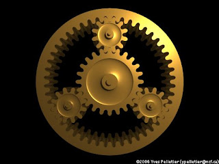
Planetary Gear


Planetary gear is an outer gear that revolves around a central sun gear. Planetary gears can produce different gear ratios depending on which gear is used as the input, which one is used as the output.

Materials Used
The gears can be constructed from a variety of materials including : 

  • Stainless steel
  • Hardened steel
  • Cast iron
  • Aluminum
The gears are suitable for reduction of high RPM electric motors for use in high-torque low RPM applications. These gears are used in precision instruments because of their reliability and accuracy.

Use of Planetary Gears
These gears are the most widely used gears having diverse applications including : 

  • Sugar industry
  • Power industry
  • Wind turbines
  • Marine industry
  • Agriculture industry


Internal Gear


An internal gear is a hollow gear with teeth cut on its internal surface. The teeth in such a gear project inwards instead of outwards from the rim.
Materials Used
There is a variety of materials being used to manufacture internal gears depending on the end application. Some of the popularly used materials are : 

  • Plastic
  • Aluminum alloys
  • Cast iron
  • Stainless steel
The teeth in such gears can either be spur or helical. The internal teeth have a concave shape with a base thicker than that of an external gear. The convex shape and a strong base help in making the teeth stronger and also creating less noise.

Advantages of Internal Gear 

  • The gears are specially designed to accommodate a wide range of equipment.
  • The gears are cost-effective and ideal for a broad range of light-duty applications.
  • The non-binding tooth design ensures smooth and quiet operation.
Use of Internal Gears 
  • Light duty applications
  • Rollers
  • Indexing


External Gear


One of the simplest and most used gear units, external gears are extensively used in gear pumps and other industrial products for smooth functioning. These gears have straight teeth parallel to the axis. The teeth transmit rotary motion between parallel shafts.
Materials Used
The gears can be constructed from a variety of materials including : 

  • Stainless steel
  • Hardened steel
  • Cast iron
  • Aluminum
The kind of material used in manufacturing these gears depends on the end use they are being put to.

Use of External Gears
These gears are used in diverse fields including : 

  • Coal industry
  • Mining
  • Steel plants
  • Paper and pulp industry

Wednesday, 27 July 2016

TIPS FOR DRIVING IN RAIN

Driving in the Rain


Driving in the rain is not as easy as driving under a clear weather. When the road is wet
, the tires lose their grip on the road and your perception is considerably reduced – it is harder to see other vehicles, road signs and the road itself. In case you get into this situation, try to drive the car carefully. Here are some tips for arriving at your destination safely if you must travel when the weather is less than favourable.

1. The first tip to consider when faced with rain is to maintain your speed at a moderate level. This would protect you since the roads are more slippery due to the flowing water.


2. Turn on your headlights even in a light rain. It helps you see the road as well as let other drivers to know your presence from a distance and avoid an accident.


3. Stay toward the middle lane as water tends to puddle in the outside lanes. If you go through these large puddles, you may be harming your engine by allowing water to splatter into it.


4. Try to stay away from large tires vehicles such as trucks and buses. The tires of these vehicles can cause a larger amount of water to spray from them, which could impair your vision. Be careful when passing them as well; if you must overtake, do so safely and quickly.


5. Never drive beyond the limits of visibility. If the rain becomes too heavy that you can barely see the car in front of you, pull over to a safe place and wait until the rain subsides.


6. Make sure that the windshield wipers are in working condition before you drive against the falling rain. Ensure to change the wiper blades when needed. This tool offers greater visibility even with the heavy rainstorm.


7. Brake earlier with lesser force than you would normally. This increases the stopping distance between you and the vehicle ahead, and signals to the driver behind that you’re slowing down.


8. Make sure to prepare your car for the drive if you know that you are going to be driving in rainy conditions. Apply a coat of rain-repellent on your windshield, as it will improve your visibility in the rain. Also be sure that windshield wiper fluidbottle is full, as this can help you to remove any dirt that may come from the wet road conditions.
Monsoon Tips from Ford India
Check your car's condition. The brakes, steering system, tyre pressures, tyre tread depth and defroster operation should be checked regularly so that you're ready to deal with a downpour.
Every car should have a good emergency kit. Breakdowns can be stressful. Taking a few steps in advance can save you time, emergency service costs and a headache.
Have an emergency kit ready for many different situations. The kit should meet your individual needs and be equipped with items ranging from spares, torch, fuses, tyre inflators, to safety kits and other items to attract or provide help.
Make sure that your wipers are in good condition amnd functioning properly. If the blades are brittle or daaged, replace them before the rains begin. Allow sufficient wetting of the windscreen prior to using the wipers to avoid scratching of the windscreen owing to dry wipe.
Use the windshield washer fluid as recommended by the manufacturer. Using a blend of water and washer fluid will clean the windscreen more effectively than washing with plain water.
Tyre pressures: Maintain correct cold tyre pressures as recommended in the owner's manual  for different loads. This is even more critical for monsoon conditions since the traction is paramount for vehicle stability.
Windscreen fogging: Use the de-frost mode with AC ON, in fresh air mode to clear the windscreen of condensation whenever the windscreen gets fogged up. Also use the rear heated window option, if present, since rear visibility improves. Refer to the owner's manual for usage.
Drive carefully! Pay attention to your speed and check your tyres. At high speeds, the rains create a fine sheet of water between the tyre and the road surface, which can cause the driver to lose control. This phenomenon is known as 'aqua-planing' and is aggravated by excessively worn tyres. Check the tyre tread depth (in the TWI area) and confirm that the depth is within the minimum allowance. The tyre tread helps in throwing out excessive water between the tyre and road ensuring adequate grip.
Keep the headlights on. When driving in rain, switch the headlights on at a low beam. It will increase your visibility and allow other drivers to notice you from a distance.