Monday, 25 July 2016

SHELL MOULDING

Introduction:-

It is a process  in which the sand is mixed with a thermo setting resin is allowed to come into contact a heated metallic pattern plate ‘so that a
them and strong shell of mould is formed around  the pattern’ then she is removed the pattern and the cope and drag are remove together and kept in a flask with the necessary back up material and the molten metal is pored into the mould.
Generally dry and fin sand which is completely free of the clay is used for preparing the shell mould in are the phenol formaldehyde rising combined with sand they hare very high strength and resistance through heat.


Steps  Involved:-

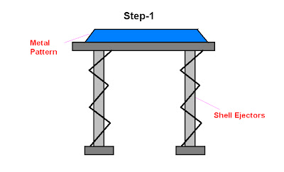
Step 1:
A metal pattern having the profile of the required casting is heated to 180°-260°c in an own maintained at 300°-400°c pattern after being heated is taken out of the own and sprayed with a solution of a lubricating agent containing silicon. It is necessary to prevent the shell from sticking to the metal pattern.
Step 2:
Metal pattern(made up of iron or steel )is then turned faced down and clamped over the open end of the dump box.

Step 3:
the dump box is inverted so that dry sand raisin mixture falls on the face of hot metal pattern . the raisin the raisin softens and fuses to form a soft and uniform  sand mixture in contact with the pattern gets heat up .the   rasinsoftens and fuses to form a soft and uniform shell of about 6mm thickness on the surface of pattern.

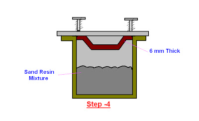


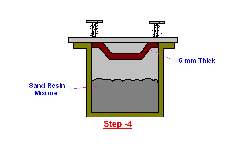
Step 4:
As the dump box is turned to its original position. Excess sand resin mixture falls beak into the dump box leaving a shell adhering closely to the pattern


Step 5:
The shell is then stripped from the pattern plate with the help of ejector pins which are an integral part of the metal pattern 

Step 6:
After the shells so obtained have cooled. Two meeting shell are securely fastened together to from a complete mould.

Saturday, 23 July 2016

WHAT IS CENTRE OF GRAVITY AND CENTROID OF A BODY?

Centre of gravity

Centre of gravity of a body is defined as the point through which the whole weight of the body acts. A body can have only one centre of
gravity for all positions of the body. It is represented or denoted by C.G. or G.

Centroid

The point, at which the total area of a plane figure (such as rectangle, triangle, square, quadrilateral, circle etc) is assumed to be concentrated, is called the centroid of that area. The centroid is also represented by C.G. or G.The centroid and centre of gravity are at the same point. 

Centroid or centre of gravity of simple plane figures:

  • The C.G. of a uniform rod lies at its middle point.
 What is Centre of Gravity and Centroid of a Body?

  • The C.G. of a triangle lies at the point where all the three medians intersect each other.
 What is Centre of Gravity and Centroid of a Body?

  • The C.G. of a rectangle (or a parallelogram or a square) lies at the point where its diagonals intersect each other. It is also the point of intersection of the middle points of the opposite sides.
 What is Centre of Gravity and Centroid of a Body?

  • The C.G. of a circle lies at its centre.  
 What is Centre of Gravity and Centroid of a Body?

DIFFERENT TYPES OF CARS ACCORDING TO BODY STYLES

Body of a car decides the space available for passenger and language in the car. There are various type of body used in Indian market. And they are given below.


1. Hatchback

Hatchbacks are vehicles with a separate engine area, and passenger area (or two boxes), the luggage area is enclosed with the passenger area behind the rear seats.

Example: Nano, Indica, Jazz, Punto etc.


2. Sedan/Notchback

Sedan are basically vehicles with an engine area, passenger area, and boot area (or three box), all separate.

Example: Indigo Manza, Swift Dzire etc.

    3. Estate/Station Wagon

    Estates or Station wagons are modified saloon vehicles by combining the boot with passenger area & extending it till the roof. The boot area is significantly larger and does not have third row seating. This makes it convenient to carry big objects.

    Example: Indigo Marina, Octavia Combi etc.


    4. Multi Purpose Vehicle (MPV) / Multi Utility Vehicle (MUV)

    MPV (Multi-Purpose Vehicles) or MUV (Multi Utility Vehicles) can have the engine, passenger area and boot area enclosed together or they can have the engine area separate and the passenger and boot area enclosed. MUV/MPV can also have third row of seating. These vehicles are two wheel drive.

    Example: Sumo Grande, Tata Tavera, Tata Innova etc.

    What is Chassis in Automobile? How Many Types of Car According to the Body Style?

    5. Sport Utility Vehicle (SUV)

    These vehicle have large tyres, higher seating, higher ground clearance. The engine area is separate and the passenger and boot area are enclosed together. These vehicles are either equipped with 4 wheel drive or has as an option of 4 wheel drive.

    Example: Safari, Scorpio, Gypsy, Fortuner.
      What is Chassis in Automobile? How Many Types of Car According to the Body Style?

      6. Pick-Up Truck

      These vehicle have large tyres, higher seating capacity, higher ground clearance. The engine area is separate and the passenger compartment available in single or double cab configurations. Also, luggage loading bay is available behind the passenger compartment. These vehicles are either equipped with 4 wheel drive or has as an option of 4 wheel drive.

      Example: Xenon, Scorpio Getaway etc.
        What is Chassis in Automobile? How Many Types of Car According to the Body Style?

        7. Van

        The engine is placed below the passenger area. Vans can also have Third row of seating. They are also taller and generally more spacious.

        Example: Winger, Ace Magic, Omni etc.

          What is Chassis in Automobile? How Many Types of Car According to the Body Style?


          Thursday, 21 July 2016

          TUBELESS TYRES

          Tubeless tires or tyres are pneumatic tires that do not require a separate inner tube.


          The traditional tyre comes with tube which is placed between the wheel rim and the tyre. Why the tube is placed there? This tube is filled with air. So, the inflated tubes help the tyres to be in shape and hold the weight of the vehicle. This type of tyre has been used till date for almost all types of vehicles. But, due to some drawbacks, the tubeless tyre is replacing the normal ones and gaining popularity among drivers.

          Disadvantages of Tube tyres:

          * Susceptible to punctures easily
          * Get flat on puncture quickly
          * If run on a flat, the tube valve gets damaged and requires a replacement
          * Cannot be run on higher speeds


          In a tubeless tire, the tire and the rim of the wheel form an airtight seal, with the valve being directly mounted on the rim.If a tubeless tire gets a small puncture, air escapes only through the [punctured] hole, leading to a gentle deflation.Conversely, an inner tube could potentially burst like a balloon, leading to a rapid deflation of the tire which could result in sudden loss of control of the vehicle.


          Advantages of Tubeless Tyres:
          The tubeless tyres are capturing the marketing and replacing the old ones. The advantages of tubeless tyre are as follows-
          1. No Problems of Tube-
          The name suggests the benefit. It is tubeless, so you won’t face any hazards regarding tubes that you have faced earlier with tube tyre.
          2. Balance Weight Is Required Less-
          One of the most important advantages of this tyre is that it weighs less. Therefore, the chance of unbalance for the tubes is lesser.
          3. Fuel Efficient-
          While buying a car, you must check it out whether it has components that save fuel. Otherwise, you’ll have a big hole in your pocket. Tubeless tyre is fuel-friendly. As there is no tube, it is lightweight and therefore, fuel efficient.
          4. Better Safety-
          While driving a car, you must take every safety measures to avoid accidents. Tubeless tyre makes your driving easy and safe. How? Actually, if the tyre gets punctured, the air leakage is much slower. And it leaks only through the hole. Therefore, driver gets much time to control the vehicle. In case of normal tyres, the tube burst like a balloon and it causes rapid deflation. Driver can lose control and can cause accidents.
          5. Cost Saving-
          While no tube is required, you don’t need to pay extra for tubeless tyre. Therefore, it is obviously saves money.
          6. Better Heat Dissipation-
          Earlier, the tube tyres got damaged frequently due to its friction with the tyre wall and inner tube. Besides, it also generated immense heat. Now, in tubeless tyre, air comes in direct contact with the rim. So, lesser heat is produced. Thus, the longevity of your tyres is increased.

          INTRODUCTION TO CRYOGENIC SYSTEMS

          Introduction
          The word cryogenics means, literally, the production of icy cold; how­ever, the term is used today as a synonym for low temperatures.
          The point on the temperature scale at which refrigeration in the ordinary sense of the term ends and cryogenics begins is not sharply defined. The workers at the National Bureau of Standards at Boulder, Colorado, have chosen to consider the field of cryogenics as that involving temperatures below -150°C (123 K) or - 240°F (2200R). This is a logical dividing line, because the normal boiling points of the so-called permanent gases, such as helium, hydrogen, neon, nitrogen, oxygen, and air, lie below - 150°C, while the Freon refrigerants, hydrogen sulfide, ammonia, and other con­ventional refrigerants all boil at temperatures above -150°C.


          In the field of cryogenic engineering, one is concerned with developing and improving low-temperature techniques, processes, and equipment. As contrasted to low-temperature physics, cryogenic engineering primarily involves the practical utilization of low-temperature phenomena, rather than basic research, although the dividing line between the two fields is not always clear-cut. The engineer should be familiar with physical phenomena in order to know How to utilize them effectively; the physicist should be familiar with engineering principles in order to design experiments and apparatus.

          Present areas involving cryogenic engineering
          Present-day applications of cryogenic technology are widely varied, both in scope and in magnitude. Some of the areas involving cryogenic engineering include:
          1.Rocket propulsion systems. All the large United States launch vehicles use liquid oxygen as the oxidizer. The Space Shuttle propulsion system uses both cryogenic fluids, liquid oxygen, and liquid hydrogen.
          2.Studies in high-energy physics. The hydrogen bubble chamber uses liquid hydrogen in the detection and study of high-energy particles produced in large particle accelerators.
          3. Electronics. Sensitive microwave amplifiers, called masers, are cooled to liquid-nitrogen or liquid-helium· temperatures so that thermal vibrations of the atoms of the amplifier element do not seriously interfere with absorption and emission of microwave energy. Cryogenically cooled masers have been used in missile detectors, in radio astronomy to listen to faraway galaxies, and in space communication systems.

          VALVE MECHANISM IN ENGINES

          Introduction :-
          Every cylinder of an automobile engine has one inlet valve for admission of charge and one exhaust valve for escape of burned gases.
          However, in some modern cars two  inlet valves and two exhaust valves are being provided per cylinder to achieve high volumetric efficiency in high speed engines. The most common mushroom type poppet valve used in automotive engines is shown in Figure below. There are very strict requirements on the geometry, material of construction and speed of opening and closing of valves as these are exposed to very high temperatures (especially exhaust valve) and pressure drop through them affects the volumetric and overall efficiency the engine.


          Poppet Valve


          The common valve mechanism to operate the valves are
          1.         Valve mechanism in engine block
          2.         Valve-operating mechanism for valve in cylinder head
          3.         Hydraulic valve lifter

          4.         Mechanism with eccentric rocker arm

          1.Valve operating Mechanism for Valves in the Engine Block (L-T- and F-head Design)
          When the cam rotates, it lifts the tappet which in turn lifts the valve to open position, connecting the valve port with the combustion chamber. the valve tappet clearance between the valve lifter and the valve stem allows for expansion of valve stem and other parts as the engine becomes heated. It can be adjusted by turning the tappet-adjusting screw. In non-adjustable type, the tappet clearance is adjusted by grinding the bottom of the valve steam.

          Valve operating Mechanism for Valves in the Engine Block

          2.Valve-operating Mechanism for Valve in Cylinder Head (Overhead Valves of I and F-head design)
          The cam lifts the valve lifter which actuates the push-rod. This action rotates the rocker arm and pushes the valve stem to open the valve.

          3.Hydraulic Valve Lifter
          In order to avoid valve-tappet clearance so that minimum noise is produced, a hydraulic valve lifter is used. The tappet acts as an oil reservoir which receives lubricating oil. A piston is connected to the push rod and moves in a cylinder which is connected to the oil reservoir through a ball-check valve. When the cam lifts the tappet, the ball-check valve closes the oil drain from cylinder to reservoir and causes the entire tappet unit to lift the push rod to open the valve.


          4.Eccentric Rocker Arm
          The position of an eccentric held in the rocker arm is controlled by a oil-operated plunger and a spring and ensures zero valve-tappet clearance


          Tuesday, 19 July 2016

          STEERING SYSTEM

          FUNCTION AND PRINCIPLE 
          The purpose of the steering system is to allow the driver to control the direction of the vehicle by turning the front wheels. This is done by means
          of steering wheel, a steering column which transmits the rotation of the steering wheel to the steering gears, the steering gears which increase the rotational force of the steering wheel in order to transmit greater torque to the steering linkage, and the steering linkage which transmits the steering gear movement to the front wheels. The steering system configuration depends on vehicle design (the drive train and suspension system used, whether it is a passenger car or a commercial vehicle, etc.). At present, the rack-and-pinion type and the recirculation-ball types are in use. 


          Requirements of steering system
          The steering system plays, together with the suspension system, an important role in ensuring easy, comfortable driving all the way from the low speed range to the high speed ranges. The drive train transmits the power from the engine to the driving wheels to move the car forward; the steering system steers the car in the desired direction; and the brake system ensures positive, stable slowing and stopping.
          1.Excellent maneuverability. When the car is cornering on narrow, twisting road, the steering system must be able to turn the front wheels sharply yet easily and smoothly.
          2.Proper steering effort. If nothing is done to prevent it, steering effort will be greater when the car is stopped and will decrease as the speed of the car increases.  Therefore, in order to obtain easier steering and better feel of the road, the steering should be made lighter at low speeds and heavier at high speeds.
          3.Smooth recovery. While the car is turning, the driver must hold the steering wheel firmly. After the turn is completed, however, recovery that is the return of the wheels to the straight-ahead position should occur smoothly as the driver relaxes the force with which he is turning the steering wheel.
          4.Minimum transmission of shock from road surface. Loss of steering wheel control and transmission of kickback due to road surface roughen must not occur.


          Principle
          The relative motion between the wheels of a vehicle at the road surface should be of a pure rolling type so that wear of the tires is minimum and uniform. When the vehicle is moving on a curved path, the steering gear must be so designed that the paths of the points of contact of each wheel with the ground are concentric circular ares. For proper steering the axis of rotation of all the wheels should meet at G i.e. the instantaneous centre of rotation of the vehicle.


          There are two types of steering gear mechanisms:
          1. Davis steering gear.
          2. Ackermann steering gear.
          The main difference between the two steering gear mechanisms is that the Davis steering gear has sliding pairs, whereas the Ackermann steering gear has only turning pairs. The sliding pair has more friction than the turning pair, therefore, the Davis steering gear will wear out earlier and become inaccurate after certain time. Although, the Ackermann steering gear is not mathematically accurate except in the positions, contrary to the Davis steering gear which is mathematically correct in all positions. However, the Ackermann steering gear is preferred to the Davis steering gear.