Wednesday, 28 January 2015

REGENERATIVE BRAKING SYSTEM

Every time we step on our car's brakes, we are wasting energy.So when your car slows down, the kinetic energy that was propelling it forward has to go somewhere. Most of it simply dissipates as heat and becomes useless. That energy, which could have been used to do work, is essentially wasted.

Regenerative braking is used on automobiles to recoup some of the energy that is lost while the vehicle is stopping. This technology is used on hybrid vehicles that use both gas and electricity as sources of power. The energy that is recouped during braking is saved in a storage battery and used later to power the motor whenever the vehicle is using its electric power source.Hybrids and all-electric vehicles create their own power for battery recharging through a process known as regenerative braking (regen mode).Simply it means means capturing the vehicle's momentum (kinetic energy) and turning it into electricity that recharges (regenerates) the onboard battery as the vehicle is slowing down and/or stopping. It is this charged battery that in turn powers the vehicle's electric traction motor.

At present, these kinds of brakes are primarily found in hybrid vehicles like the Toyota Prius, and in fully electric cars, like the Tesla Roadster.However, the technology was first used in trolley cars and has subsequently found its way into such unlikely places as electric bicycles and even Formula One race cars.

How does it work?

In braking systems on conventional vehicles, friction is used to counteract the forward momentum of a moving vehicle.This friction is what turns the car's kinetic energy into heat. With regenerative brakes, on the other hand, the system that drives the vehicle does the majority of the braking. It uses completely different method of braking at slower speeds. Hybrid vehicles still use conventional brake pads at highway speeds, but electric motors help the vehicle brake during stop-and-go driving at slower speeds. As the driver applies the brakes by pressing down on a conventional brake pedal, the electric motors reverse direction. The torque created by this reversal counteracts the forward momentum and eventually stops the car.In simple words,when the driver steps on the brake pedal of an electric or hybrid vehicle, these types of brakes put the vehicle's electric motor into reverse mode, causing it to run backwards, thus slowing the car's wheels. While running backwards, the motor also acts as an electric generator, producing electricity that's then fed into the vehicle's batteries.


Advantages of regenerative braking system:-
>Increase of overall energy efficiency of a vehicle.
>Increases vehicle range.
>Cuts down on pollution related to electricity generation.
>Increases the lifespan of friction braking systems.
>Less use of traditional mechanical brakes leads to less wear over time.

Sunday, 25 January 2015

CNG ENGINE

CNG engine uses compressed natural gas to power the car. CNG is a substitute for gas and diesel fuel, and is considered to be much cheaper and cleaner than gas or diesel. Natural-gas-powered vehicles burn compressed natural gas (CNG) instead of conventional gasoline.


Why Use Compressed Natural Gas?


The benefits of CNG are lower operating costs, lower fuel costs, improved gasoline-gallon fuel economy, and almost zero smog-forming emissions. One example of a vehicle that uses CNG for its fuel is the Honda Civic Natural Gas Sedan.In addition, the CNG engine is considered to be more environmentally friendly. There are considerably less pollutants associated with compressed natural gas being ignited, and studies show that it gives off 40 percent less greenhouse gas.


The CNG Engine:-


The CNG engine uses a second fuel tank which has to be attached to the car, and is usually placed in the trunk (or other place where there is suitable room). This tank is usually very large, as it has to keep the gas used compressed. The amount of pressure may vary from engine to engine, but it is usually compressed to around 3,600 pounds per square inch. The driver can then decide which of the fuels they wish to use by simply pressing a switch on the dashboard. This means that the car can alternate between the different tanks, drawing fuel from either.Having a dual fuel system will ensure adequate fuel reserves in between natural gas fills. Compared to having only a gasoline engine, this additional fuel reserve will extend the vehicle’s driving range. Drivers can switch from CNG to gasoline even while driving, idling or parked. Some CNG systems will automatically switch to gasoline when the natural gas level reaches a preset low pressure setting.


How the CNG Engine works?


Once the driver selects the CNG tank, CNG is fed into the high pressure cylinders through the natural gas receptacle.The compressed gas in the tank is pulled through a series of highly pressurized lines until it reaches the regulator.Inside the regulator, the pressure on the gas is lessened until it matches the amount needed by the fuel injection system of the car's engine. Once the gas has reached an acceptable pressure, the solenoid valve allows the gas to move into the fuel injection system and from there into the engine.Just as with gasoline, once the engine has received the gas, it is ignited in the combustion chamber, and this provides the energy to power the car forward.


You can also convert your gas engine to CNG, a diesel conversion though doesn’t have problems with predetonation or need knock sensors like a gas conversion. Diesel engines is built for heavy duty use, exploding diesel with heat and combustion not spark. This all makes diesel engines the ideal CNG conversion candidate. 

Tuesday, 20 January 2015

VARIOUS COMPONENTS OF AN ENGINE

Internal combustion engines are made from various parts.Each part has its own location and function for proper working of engine.. There are hundreds of components which have to perform their functions satisfactorily to produce output power. The major components of the engine and their functions are briefly described below:-


1.)Cylinder Block:

The cylinder block is the largest part of the engine. Its upper section carries the cylinders and pistons. Normally, the lower section forms the crankcase, and supports the crankshaft.It is the main supporting structure for the various components. The cylinders of a multicylinder engine are cast as a single unit, called cylinder block.It is the portion of the engine between the cylinder head and sump (oil pan)and is the supporting structure for the entire engine. All the engine parts are mounted on it or in it and this holds the parts in alignment.Cylinder blocks made of aluminum are lighter than cast-iron blocks of the same size. They usually have cast-iron liners which provide a hard-wearing surface for pistons and piston rings.
 
Function- In the bore of cylinder the fresh charge of air-fuel mixture is ignited,compressed by piston and expanded to give power to piston.

2.)Cylinder Head:

It carries inlet and exhaust valve.Fresh charge is admitted through inlet valve and burnt gases are exhausted from exhaust valve.In case of petrol engine,a spark plug and in case of diesel engine,a injector is also mounted on cylinder head.
3.)Cylinder: 
As the name implies it is a cylindrical vessel or space in which the piston makes a reciprocating motion.The varying volume created in the cylinder during the operation of the engine is filled with the working fluid and subjected to different thermodynamic processes. The cylinder is supported in the cylinder block.
4.)Piston:
This is a pressure-tight cylindrical plunger which is subjected to the expanding gas pressure.It is fitted into the cylinder forming the moving boundary of the combustion system. It fits perfectly into the cylinder providing a gas-tight space with the piston rings and the lubricant. It forms the first link in transmitting the gas forces to the output shaft.
Function-During suction stroke,it sucks the fresh charge of air-fuel mixture through inlet valve and compresses during the compression stroke inside the cylinder.This way piston receives power from the expanding gases after ignition in cylinder.Also forces the burnt exhaust gases out of the cylinder through exhaust valve.

5.)Piston rings:
 These are circular rings which seal the gaps made between the piston and the cylinder, their object being to prevent gas escaping and to control the amount of lubricant which is allowed to reach the top of the cylinder.
Function-It prevents the compressed charge of fuel-air mixture from leaking to the other side of the piston.Oil rings,is used for removing lubricating oil from the cylinder after lubrication.This ring prevents the excess oil to mix with charge.
5.)Connecting Rod: 
It interconnects the piston and the crankshaft and transmits the gas forces from the piston to the crankshaft. The two ends of the connecting rod are called as small end and the big end. Small end is connected to the piston by gudgeon pin and the big end is connected to the crankshaft by crankpin.
Function-It changes the reciprocating motion of piston into rotary motion at crankshaft.This way connecting rod transmits the power produced at piston to crankshaft.

6.)Crankshaft:
It converts the reciprocating motion of the piston into useful rotary motion of the output shaft. In the crankshaft of a single cylinder engine there are a pair of crank arms and balance weights.A simple crankshaft consists of a circular-sectioned shaft which is bent or cranked to form two perpendicular crank-arms and an offset big-end journal. The unbent part of the shaft provides the main journals. The crankshaft is indirectly linked by the connecting-rod to the piston - this enables the straight-line motion of the piston to be transformed into a rotary motion at the crankshaft about the main-journal axis.
Function-Receives oscillating motion from connecting rod and gives a rotary motion to the main shaft.It also drives the camshaft which actuate the valves of the engine

7.)Camshaft:
The camshaft and its associated parts control the opening and closing of the two valves. The associated parts are push rods, rocker arms, valve springs and tappets. This shaft also provides the drive to the ignition system. The camshaft is driven by the crankshaft through timing gears.
Function-It takes driving force from crankshaft through gear train or chain and operates the inlet valve as well as exhaust valve with the help of cam followers,push rod and rocker arms.

8.)Spark Plug
Function-This device is used in petrol engine only and ignite the charge of fuel for combustion.
9.) Fuel Injector
Function-This device is used in diesel engine only and delivers fuel in fine spray under pressure
.


Sunday, 18 January 2015

DISC BRAKE


Disc brakes use a flat, disk-shaped metal rotor that spins with the wheel. When the brakes are applied, a caliper squeezes the brake pads against the disc (just as you would stop a spinning disc by squeezing it between your fingers), slowing the wheel.
Disc brakes use the same principle as bicycle handbrakes, but on a bike the brake pads press against the wheel itself. On a car, the disc is part of the hub to which the wheel is mounted. The disc, technically called a rotor, is clearly visible through spoked wheels.Disc brakes generate amazing stopping power even in the worst conditions because they utilize rotors (photo) attached to the wheel hubs, and calipers attached to the frame containing specially designed pads 
The main components of a disc brake are:

  • The brake pads
  • The caliper, which contains a piston
  • The rotor, which is mounted to the hub

How Disc Brakes Work?

On a disc brake, the fluid from the master cylinder is forced into a caliper where it presses against a piston. The piston, in turn, squeezes two brake pads against the disc (rotor) which is attached to the wheel, forcing it to slow down or stop. 

This process is similar to a bicycle brake where two rubber pads rub against the wheel rim to create stopping friction.

Why do disc brake have holes in them?

Due to following reasons :-

>These holes significantly increasing the grab or friction of the brake caliper pads. 
>Reduce the weight of whole assembly.
>For proper heat dissipation generated during braking.
>The holes are spaced in such a way that the calipers used in the brake wear out uniformly, to ensure maximum longevity.

Saturday, 17 January 2015

PELTON TURBINE

A turbine converts energy in the form of falling water into rotating shaft power. The selection of the best turbine for any particular hydro site depends on the site characteristics, the dominant ones being the head and flow available.

The Pelton type turbine is usually the preferred turbine for hydropower, when the available water source has relatively high hydraulic head at low flow rates.They have the advantages such as compact structure, small size, high efficiency, low operation maintenance cost, low cost because of less excavation and less investments, etc. and disadvantages like inadequate energy recovery and lower efficiency than other types of turbines.In a Pelton Turbine or Pelton Wheel water jets impact on the blades of the turbine making the wheel rotate, producing torque and power. 

Pelton Turbine – The Basic Working Principle


Working principle of Pelton turbine is simple. When a high speed water jet injected through a nozzle hits buckets of Pelton wheel; it induces an impulsive force. This force makes the turbine rotate. The rotating shaft runs a generator and produces electricity.

In large scale hydro installation Pelton turbines are normally only considered for heads above 150 m, but for micro-hydro applications Pelton turbines can be used effectively at heads down to about 20 m. Pelton turbines are not used at lower heads because their rotational speeds becomes very slow and the runner required is very large and unwieldy. If runner size and low speed do not pose a problem for a particular installation, then a Pelton turbine can be used efficiently with fairly low heads.


Friday, 16 January 2015

VERY IMPORTANT INTERVIEW QUESTION:- Q:-Difference between internal combustion engines and external combustion engines?

VERY IMPORTANT INTERVIEW QUESTION:-

Q:-Difference between internal combustion engines and external combustion engines? 

Answer:- In an *Internal Combustion Engine*, the Fuel is burnt in the cylinder or vessel eg. Diesel or Petrol engine used in Cars.
In an *External Combustion Engine*, the internal working fuel is not burnt. Here the fluid is being heated from an external source. The fuel is heated and expanded through the internal mechanism of the engine resulting in work. eg. Steam Turbine, Steam engine Trains.
* Internal engine has its energy ignited in the cylinder. like 99.9% of engines today.
* An external combustion example is a steam engine where the heating process is done in an boiler out side the engine.

So in fact we can define internal combustion engine develops its operating pressure by burning fuel directly in the engine. Gasoline engines, Wankel engines, diesels, gas turbines are all internal combustion. External combustion engines burn the fuel outside the engine and use it to heat an operating fluid which then is used to operate the engine. Steam locomotives, steam turbines, and Stirling engines are external combustion


Monday, 12 January 2015

PROPERTIES OF SYSTEM

PROPERTIES OF SYSTEM:

A property of a system is a characteristic of the system which depends upon its state, but not upon how the state is reached. There are two sorts of property :

1. Intensive properties.These properties do not depend on the mass of the system.Examples: Temperature and pressure.

2. Extensive properties.These properties depend on the mass of the system. Example:Volume. Extensive properties are often divided by mass associated with them to obtain the intensive properties. For example, if the volume of a system of mass m is V, then the specific volume of matter within the system is V/m= v which is an intensive property.


BEARINGS

Bearings:-

It is a machine element that constrains relative motion between moving parts to only the desired motion. The design of the bearing may, for example, provide for free linear movement of the moving part or for free rotation around a fixed axis ; or, it may"prevent" a motion by controlling the vectors of normal forces that bear on the moving parts. Bearings are classified broadly according to the type of operation, the motions allowed, or to the directions of the loads (forces) applied to the parts.

Basic Definitions Used in Engine Terminology


Basic Definitions Used in Engine Terminology:-

1. Top dead center (T.D.C.)
In a reciprocating engine the piston moves to and fro motion in the cylinder. When the piston moves upper direction in the cylinder, a point at which the piston comes to rest or change its direction known as top dead center. It is situated at top end of cylinder.

2. Bottom dead center (B.D.C.)
When the piston moves in downward direction, a point at which the piston come to rest or change its direction known as bottom dead center. It is situated in bottom side of cylinder.

3. Stroke (L)
The maximum distance travel by the piston in single direction is known as stroke. It is the distance between top dead center and bottom dead center.

4. Bore (b)
The inner diameter of cylinder known as bore of cylinder.

5. Maximum or total volume of cylinder (Vtotal)
It is the volume of cylinder when the piston is at bottom dead center. Generally, it is measure in centimeter cube (c.c.).

6. Minimum or clearance volume of cylinder (Vclearance)
It is the volume of cylinder when the piston is at top dead center.

7. Swept or displace volume (Vswept)
It is the volume which swept by the piston. The difference between total volume and clearance volume is known as swept volume.

Swept volume = Total volume - Clearance volume

8. Compression ratio
The ratio of maximum volume to minimum volume of cylinder is known as the compression ratio. It is 8 to 12 for spark ignition engine and 12 to 24 for compression ignition engine.

Compression ratio = Total volume / Clearance volume

9. Ignition delay
It is the time interval between the ignition start (spark plug start in S.I. engine and inject fuel in C.I. engine) and the actual combustion starts.

10.)Stroke bore ratio

Stroke bore ratio is the ratio of bore (diameter of cylinder) to length of stroke. It is generally equal to one for small engine and less than one for large engine.

Stroke bore ratio = inner diameter of cylinder / length of stroke

Four Stroke Cycle Spark Ignition (petrol) Engine

Gasoline or petrol engines are also known as spark-ignition (S.I.) engines. Petrol engines take in a flammable mixture of air and petrol which is ignited by a timed spark when the charge is compressed. The first four stroke spark-ignition (S.I.) engine was built in 1876 by Nicolaus August Otto, a self-taught German engineer at the Gas-motoreufabrik Deutz factory near Cologne, for many years the largest manufacturer of internal-combustion engines in the world. 

As the name suggest the Four Stroke Petrol Engine uses a cycle of four strokes and petrol as the fuel. Each cycle includes 2 rotations of the crankshaft and four strokes, namely:
1.An Intake Stroke
2.A Compression Stroke
3.A Combustion Stroke also called Power Stroke
4.An Exhaust Stroke 

1.Intake Stroke
As the name suggests in this stroke the intake of fuel takes place. When the engine starts, the piston descends to the cylinder's bottom from the top. Thus the pressure inside the cylinder reduces. Now the intake valve opens and the fuel and air mixture enters the cylinder. The valve then closes.

2.Compression Stroke
This stroke is known as compression stroke because the compression of the fuel mixture takes place at this stage. When the intake valve closes (exhaust valve is already closed), the piston forced back to the top of the cylinder and the fuel mixture gets compressed. The compression is around 1/8th of the original volume. An engine is considered more efficient if its compression ratio is higher.

3.Combustion/Power Stroke
Now in case of petrol engine when the fuel mixture compresses to the maximum value the spark plug produces spark which ignites the fuel mixture. The combustion leads to the production of high pressure gases. Due to this tremendous force the piston is driven back to the bottom of the cylinder. As the piston moves downwards, the crankshaft rotates which rotates the wheels of the vehicle.

4.Exhaust Stroke
As the wheel moves to the bottom the exhaust valve opens up and due to the momentum gained by the wheel the piston is pushed back to the top of the cylinder. The gases due to combustion are hence expelled out of the cylinder into the atmosphere through the exhaust valve. 

The exhaust valve closes after the exhaust stroke and again the intake valve opens and the four strokes are repeated.

TRENDING NEWS

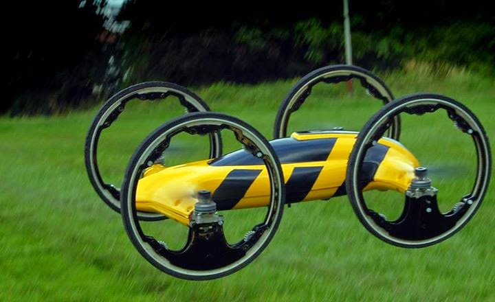
Why limit your drone to the ground/to the air when it can handle both? 

B is, at its core, a quadrocopter that sports four large wheels, nearly 9-inches in diameter, and that takes to the air at a whim when faced with unsurmountable obstacles thanks to 7-inch props between each wheel. Otherwise, it’s incredibly resilient thanks to the protective nature of the wheels, prop-savers, and a solid polycarbonate shell, features an on-board HD 1280×720 camera with Micro SD compatibility, and runs for a respectable 15 minutes per charge. Plus, there’s absolutely nothing else like it, so this is one Kickstarter project we especially want to see succeed.

Sunday, 11 January 2015

PORSCHE 918 SPYDER

PORSCHE 918 SPYDER :-

The Porsche 918 Spyder is a mid-engined plug-in hybrid supercar designed by Porsche. 

The Spyder is powered by a 4.6 liter V8 engine, developing 608 horsepower (453 kW), with two electric motors delivering an additional 279 horsepower (208 kW) for a combined output of 887 horsepower (661 kW). 

The 918 Spyder's 6.8 kWh lithium-ion battery pack delivers an all-electric range of 12 mi (19 km) under EPA's five-cycle tests.

The car has a top speed of around 340 km/h (210 mph).
The 918 Spyder is a limited edition supercar, and Porsche plans to manufacture 918 units as a 2014 model year.

Production began on September 18, 2013, with deliveries initially scheduled to begin in December 2013.

It is the second plug-in hybrid car from Porsche, after the 2014 Panamera S E-Hybrid. The 918 Spyder was sold out in December 2014. The country with the most orders is the United States with 297 units.


POWER STEERING


Power steering is a system to aid the steering of an automobile by use of a hydraulic device (driven from the engine) that amplifies the turning moment, or torque, applied to the steering wheel by the driver.It is relatively difficult to turn the steering wheel when the vehicle is to be stopped. Turning the wheel requires a certain amount of upper body strength. To reduce the torque required from the driver as cars became heavier and tires softer, gears were introduced between the steering wheel shaft and the linkage that turns the wheels.

There are two types of conventional power steering systems. The first type uses a hydraulic cylinder attached to the drag link and the chassis. A control valve is attached to the end of the drag link replacing the tie rod end and the valve actuator is connected by a tapered shaft to the pitman arm.
The second type uses a hydraulic cylinder that is an integral part of the steering gear and is connected to the recirculating ball nut located on the steering shaft. The rotary control valve is connected to a torsion bar that is part of the steering shaft. The rack and pinion steering gear hydraulic cylinder is part of the rack gear and the control valve is connected by a torsion bar to the steering shaft. In all these types of power steering, the pump delivers fluid to the control valve. The control valve opens a pressurized flow to and from the hydraulic cylinder.

Most modern power-steering systems consist of hydraulic boosts applied to either the steering linkage or the steering gear. Rotation of the steering wheel activates a valve that directs oil, pressurized by a pump driven by the engine, to act on a piston. The hydraulic boost acts only while the steering wheel is moving. 

SCREW JACK

A screw jack is a mechanical device that can increase the magnitude of an effort force.Screw jack is used in applications where linear motion is required. Lifting of any load, pushing or pulling of mechanical equipment, adjusting of tight clearances of mechanical parts can be done by screw jacks. Mechanical capacity of screw jacks is between 5kN and 2000kN. Jack screws can be used as linear motors, linear actuators, or mechanical lifts depending on type of motion.

The effort force for a screw jack when neglecting friction can be expressed as:-
F = (Q p) / (2 Ï€ R)         (1)
where
F = effort force at the end of the arm or handle (lb)
Q = weight or load (lb)
p = pitch distance or lead of thread in one turn  (in)
r = pitch radius of screw (in)
R = lever-arm radius (in)

Screw Jack Applications:-


Paper, press, printing industry
Gypsum factories
Sheet metal forming machinery
Mechanical lifting applications
Platform lifting applications
Food processing machinery
Construction sector
Bridge jacks for road and bridge lifting
Shipyards
Opening and closing of penstocks
Industrial process
Roll form machinery
Mining industry
Defense industry
Lift tables
Stage setup applications 

Saturday, 10 January 2015

Gas tungsten arc welding or TIG welding


Gas tungsten arc welding (GTAW), also known as tungsten inert gas (TIG) welding, is an arc welding process that uses a non-consumable tungsten electrode to produce the weld. The weld area is protected from atmospheric contamination by an inert shielding gas (argon or helium), and a filler metal is normally used, though some welds, known as autogenous welds, do not require it. A constant-current welding power supply produces energy which is conducted across the arc through a column of highly ionized gas and metal vapors known as a plasma. 

SUPERCHARGER

SUPERCHARGER:-

Superchargers, otherwise known as blowers, are a form of compressor driven by the engine’s crankshaft (often with a belt) to turn an impeller or rotors, which compress air to create boost.Originally built for World War II aircraft, superchargers have become very common in today's performance automotive world, and featured as original equipment on some new sports cars straight from the factory.Superchargers have become popular in recent years for several reasons, including cost efficiency, reliability, and of course, performance. Supercharging an engine often results in huge power increases in the range of 50% to 100%, making them great for racing, hauling heavy loads, or just having fun in your daily driver.

Heat exchangers (intercoolers) are frequently used in conjunction with superchargers. Compressing air increases its temperature thus making it less dense. By re-cooling the compressed volume of air before it enters, density is increased allowing even more air to be forced into the engine. Intercoolers are more important for turbo superchargers as there are two heating sources present, the act of compression and heat from exhaust gasses both increase air temperature.

What is the need of extra air by external means?

Engines combust (burn) fuel and use the energy of that combustion to do work. The more fuel that is combusted in any given time then the more energy is available to carry out the engines task. Fuel requires air (or the oxygen contained within air) to burn so if there isn’t enough air mixed with the fuel it will not burn. This also means that the amount of air entering an engine determines how much fuel can be burnt and consequently how much energy (or power) an engine can produce. Superchargers are essentially an air pump designed to cram extra air into an engine allowing it to combust more fuel than would otherwise be possible.

Many people assume that running a supercharger, and hence added intake boost, puts added strain on an engine's engine parts. This is not necessarily true, because engine damage is almost always caused by RPM. Because a supercharger helps the engine produce more power at lower RPM, supercharged engines will make the same horsepower as their naturally aspirated counterparts at substantially lower engine RPM, where today's street engine's are designed to run (around 6000 RPM). Another concern some people have towards using a supercharger is that they think it will increase the engine's compression to the point that it will cause detonation inside the combustion chamber. Detonation exists when the combustion pressure is raised so high that the inlet charge ignites itself before the spark plug fires. When this happens, combustion takes place while the piston is still traveling up in the cylinder bore, which puts tremendous loads on the piston, rod, and crank. While it is true that a supercharged engine creates boost and increases the engine's compression, most supercharger kits include a boost timing retard chip that retards the engine's ignition timing under certain conditions to prevent detonation. With some kits, detonation is not a concern, in which case the kit will not include a boost timing retard chip.

Advantages:-


1.)Increased horsepower: adding a supercharger to any engine is a quick solution to boosting power.
2.)The supercharger does not have a delay. It is always operating at the speed of the engine.So Power delivery is immediate because the supercharger is driven by the engine’s crankshaft.
3.)Supercharging systems are less complex than turbos, which require extensive modification of the exhaust system.
4.)Low RPM boost: good power at low RPM in comparison with turbochargers.
5.)Because they are less complex, and easier to work on, they are thus cheaper to install and generally cost less to service and maintain.

LATHE AND OPERATIONS ON IT


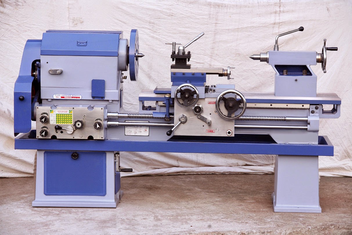
LATHE:-

A lathe is a machine tool which turns cylindrical material, touches a cutting tool to it, and cuts the material.The purpose of a lathe is to rotate a part against a tool whose position it controls. It is useful for fabricating parts and/or features that have a circular cross section. 

A typical lathe consists of bed, head stock, tail stock, tool post, carriage and feeding mechanism. Lathe is capable of performing a number of operations. 


Operations that can be performed on lathe are:-

1.)Straight turning:
Straight turning, sometimes called cylindrical turning, is the process of reducing the work diameter to a specific dimension as the carriage moves the tool along the work.


2.)Step Turning
It is an operation of producing various steps of different diameters of in the work piece.This operation is carried out in the similar way as straight turning.

3.)Facing:
Facing is the producing of a flat surface as the result of a tool's being fed across the end of the rotating workpiece.Facing is machining the ends and shoulders of a piece of stock smooth. flat, and perpendicular to the lathe axis. Facing is used to cut work to the desired length and to produce a surface from which accurate measurements may be taken. 

4.)Boring
Boring is enlarging an existing hole. The hole can be a drilled, molded, cast or a forged hole. The work piece is placed in the lathe chuck and will be spinning while the boring tool is slowly driven into the opening. Boring tools are cylindrical in shape and will have a cutting tool protruding from them. Two different boring tools can be mounted together to make two different cuts at one time.

5.)Parting:
  • Parting is the operation by which one section of a workpiece is severed from the remainder by means of a cutoff tool.

6.)Threading:
Lathe provided the first method for cutting threads by machines. Although most threads are now produced by other methods, lathes still provide the most versatile and fundamentally simple method.

7.)Knurling:
Knurling is a manufacturing process, typically conducted on a 
lathe, whereby a visually-attractive diamond-shaped (criss-cross) pattern is cut or rolled into metal. This pattern allows human hands or fingers to get a better grip on the knurled object than would be provided by the originally-smooth metal surface.

8.)Drilling:
Frequently, holes will need to be drilled using the lathe before other internal operations can be completed, such as boring, reaming, and tapping. Although the lathe is not a drilling machine, time and effort are saved by using the lathe for drilling operations instead of changing the work to another machine.

Friday, 9 January 2015

Which is the fastest car in the world?

Which is the fastest car in the world?

The Hennessey Venom GT is the fastest road car in the world, setting a mark of 270.49mph early in 2014. It beat the previous title holder, the Bugatti Veyron Super Sport, by just 0.63mph - but the record won't be officially recorded.

The official Guinness World Record requires two runs in opposite directions to work out an average speed - meaning tailwinds are taken into account - and since the Venom GT wasn't able to do this on that runway, the record books remain unchanged - the Bugatti is still technically the champion.

The Venom GT also holds the speed records for world’s fastest car from 0-300 km/h (13.63 seconds) and 0-200 mph (14.51 seconds). That's thanks to a low weight (1,244kg) and a high power output (1,244bhp) from its 7.0-litre twin-turbo V8 engine.

MECHANICAL ENGG. TERMS


ACCURATE – Without error within tolerances allowed, precise, correct,
confirming exactly to standard.

ACME THREAD – A screw thread having an included angle of 29° and
largely used for feed screws on machine tools.

ACUTE ANGLE – An angle which is less than a right angle, 90°.

ADDENDUM – The portion of the tooth of a gear that extends from the
pitch line to the outside.

ALIGN – To bring two or more components of a unit into correct positions
with respect to one another.


ALLOWANCE – The intentional or desired difference between the maximum
limits of mating parts to provide a certain class of fit.

MILLING MACHINE AND IT'S TYPE

Milling machines are an important industrial tool for machining solid materials like wood and metal.They are usually used to machine flat surfaces, but can also produce irregular surfaces. They can also be used to drill, bore, cut gears, and produce slots. The type of milling machine most commonly found in student shops is a vertical spindle machine with a swiveling head.

Milling machines can be outfitted with a number of tool heads to accomplish different machining needs. Some of these tool heads include cutters, rounding mills, fluted mills and ball end mills. Some milling machines have rotating tool ends that can change depending on the needed task—computer programming communicates with the machine when to change its tooling. 

Types of Milling Machines:-

Milling machines are categorized by their orientation to their workpiece and their degree of motion. 


Knee-Type:-

Knee-Type milling machinesemploy a vertical workspace supported by a knee, which is an adjustable vertical casting. The knee supports a saddle and can be adjusted to allow for a customizable workspace. 


Plain Vertical and Horizontal:-

Milling machines with a standard work surface can either be oriented vertically or horizontally. The tooling assembly is generally affixed on a turret and swivel, typically positioned parallel to the workspace. The turret and swivel allow the tool to move freely around the workpiece to enforce tight tolerances. 


Universal Horizontal Milling Machine:-

A universal horizontal milling machine differs from the plain horizontal type because it has a table swivel housing, which allows the table to move out 45 degrees from the standard horizontal position. This workpiece movement allows for easier angular or helical milling operations. 


Ram-Type and Universal Ram-Type Milling Machines:-

A ram-type machine is used to allow the tooling to position itself on a greater range of space with regards to the workpiece. The ram-type machine has a spindle on a movable housing, which can move within a set horizontal plane. The universal ram-type milling machine includes a swivel housing that increases the range of cutting movements.

Swivel Cutter Head Ram-Type Milling Machine:-

With a swivel cutter, a milling machine can rotate from a completely vertical to a completely horizontal position. The worktable also moves, providing the user with a very liberal degree of motion and orientation. Many swivel cutters include both automatic or hand driven settings, increasing operation options.